
Related Manuals for HP Z24q G3


Summary of Contents for HP Z24q G3
- Page 1 Maintenance and Service Guide Z24q G3 model SUMMARY This guide provides information about spare parts, removal and replacement of parts, diagnostic tests, problem troubleshooting, and more.
- Page 2 AMD is a trademark of Advanced Micro sure to read “Important Safety Information”. Devices, Inc. Bluetooth is a trademark owned by its proprietor and used by HP Inc. under license. NVIDIA is a trademark and/or registered trademark of NVIDIA Corporation in the U.S.
-
Page 3: Table Of Contents
Table of Contents 1 Getting started ................................1 Important safety information ..........................1 Important service information and precautions ....................1 RoHS (2002/95/EC) requirements .......................... 2 General descriptions .............................. 2 Firmware updates ..............................2 Before returning the repaired product to the customer ..................2 2 Monitor features ................................ -
Page 4: Getting Started
Getting started Read this chapter to learn about safety information and where to find additional HP resources. Important safety information Carefully read the cautions and notes within this document to minimize the risk of personal injury to service personnel. The cautions and notes are not exhaustive. Proper service methods are important to the safe, reliable operation of equipment. -
Page 5: Rohs (2002/95/Ec) Requirements
Level 2: Circuit board or standard parts replacement Firmware updates Firmware updates for the monitor are available at support.hp.com. If no firmware is posted, the monitor does not need a firmware update. Before returning the repaired product to the customer Perform an AC leakage current check on exposed metallic parts to be sure the product is safe to operate without the potential of electrical shock. -
Page 6: Monitor Features
For safety and regulatory information, refer to the Product Notices provided in your documentation kit. To access the latest user guides or manuals for your product, go to http://www.hp.com/support and follow the instructions to find your product. Then select Manuals. -
Page 7: Front Components
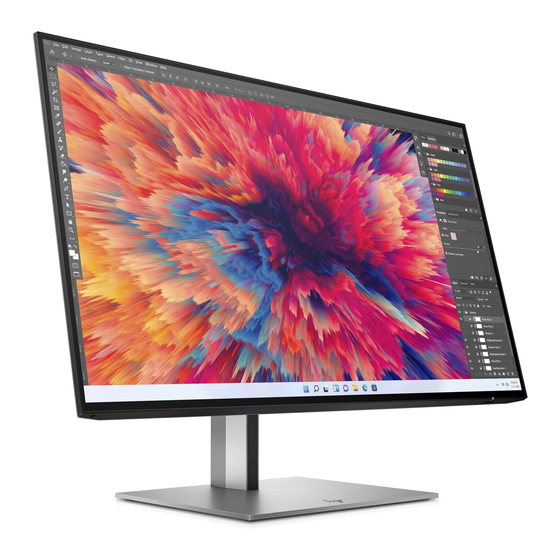
Front components To identify the components on the front of the monitor, use this illustration and table. -
Page 8: Rear And Side Components
Rear and side components To identify the components on the rear of the monitor, use this illustration and table. Table 2-2 Rear and side components and their descriptions Component Description OSD control Activates the OSD buttons so that the button labels appear on the right side of the screen. -
Page 9: Locating The Serial Number And Product Number
Locating the serial number and product number The serial number and product number are located on the rear of the monitor. You may need these numbers when contacting HP about the monitor model. For worldwide models(including India): Barcode label & Spec label... -
Page 10: Illustrated Parts Catalog
To identify the monitor major components, use this illustration and table. Table 3-1: Monitor major components and their descriptions Item Description Part number # ASSY Panel Z24q G3 #ASSY Main Chassis Z24q G3 #Power Board Z24q G3 #Interface Board Z24q G3 #Screw Machine M3*6 #Screw Cap Head M4*8... -
Page 11: How To Order Parts
#Stand Arm Lift 150 AL Z24q G3 #Stand Base Turbo Silver Z24q G3 #Double Adhesive Tape #PET Shading Lens How to order parts The HP authorized repair center can purchase the power board from HP. Power board Description HP spare part number Manufacturer part number... - Page 12 You can purchase cables from the HP part store at https://partsurfer.hp.com/Search.aspx. NOTE: HP continually improves and changes product parts. For complete and current information about supported parts for your computer, go to http://partsurfer.com, select your country or region, and then follow the on-screen instructions.
-
Page 13: Removal And Replacement Procedures
Removal and replacement procedures Adherence to these procedures and precautions is essential for proper service. Preparation for disassembly Use this information to properly prepare to disassemble and reassemble the monitor. 1) Read the “Important safety information” and “Important service information and precautions” sections in the “Getting started”... - Page 14 2) Remove Rear Cover From Display Head: Use the tool to remove the hinge cover, then Release the four screws from back bracket and remove the hinge, then Loose all the hooks by hand for pulling the rear cover 3) Remove USB BD Screws to remove USB BD: Remove the EMI gasket, then loose the two hooks by hand, then remove the cable...
- Page 15 4) Release OSD key BD from rear cover 5) Remove IO cover from display head(Remove three screws and loose three hooks by hand) 6) Remove Bracket Assembly From Display Head(remove 4pcs screws and remove three cable connectors) 7) Remove bezel bottom ASSY from display head(Remove 5pcs screws)
-
Page 16: Power Board
The power board part number is 755.08002.0001. Before removing the power board, follow these steps: ▲ Prepare the monitor for disassembly. See Preparation for disassembly on page 10. Remove the power board: 1) The HP Z24q G3 power board connector position is as follows:... - Page 17 2) Locate the part number location on the board. 3) Pin solder with soldering iron and absorber.
-
Page 18: Connector Repair
4) Lift the connector up and away from the PCB. Connector repair This procedure includes HDMI, Display Port, USB-B and USB-A connectors. The connectors are on the main board (board part number 7ZB.08001.0007). The connector identifiers are as follows: Connector Location HDMI HDMI1... -
Page 19: Dp Connector Dp1 Dp2
2) Use a hot air gun to melt the solder on the pins. 3) Lift the HDMI connector from the PCB. 4) Place the new component on the PCB. Be sure that it matches the PCB footprint. 5) Solder the new component. DP connector DP1 DP2 Repair the DP connector: 1) Use a soldering iron and a de-soldering pump to remove as much solder as possible from the pin. -
Page 20: Usb-B Connector Usb1
3) Lift the DP connector from the PCB. 4) Place the new component on the PCB. Be sure that it matches the PCB footprint. 5) Solder the new component. USB-B connector USB1 Repair the USB-B connector: 1) Use a soldering iron and a de-soldering pump to remove as much solder as possible from the pin. 2) Lift the USB-B connector from the PCB. -
Page 21: Usb-A Connector Usb4/Usb5
2) Lift the USB-A connector from the PCB. 3) Place the new component on the PCB. Be sure that it matches the PCB footprint. 4) Solder the new component. USB-A connector USB4/USB5 Repair the USB-A connector: 1) Use a soldering iron and a de-soldering pump to remove as much solder as possible from the pin. 2) Lift the USB-A connector from the PCB. -
Page 22: Support And Troubleshooting
DP out test Confirm whether image displays Computer / DVD player and other monitor USB Hub Test Confirm USB function of 4-USB Type-A working Computer or Notebook normally. Support and troubleshooting The following table lists possible problems, the possible cause or each problem, and the recommended solutions. - Page 23 displayed on screen. The monitor does The monitor’s power saving control is disabled. Open the OSD menu and not enter into a select Power select Auto- Sleep Mode and set auto- low-power sleep state. sleep to On. “OSD Lockout” is The monitor’s OSD lock function is enabled.
-
Page 24: Index
Index components RC removal, 10 front, 4 rear components, 5 rear, 5 removal connector repair, 15 power board, 13 features, 3 RC, 10 firmware updates, 2 removal and replacement procedures, 10 front components, 4 returning to customer, 2 function test, 18 RoHS (2002/95/EC) requirements, 2 how to order parts, 8 safety information, 1...
Need help?
Do you have a question about the Z24q G3 and is the answer not in the manual?
Questions and answers