Roger Technology CTRL Instruction And Warnings For The Installer
Hide thumbs
Also See for CTRL:
- Instruction and warnings for the installer (292 pages) ,
- Quick start manual (6 pages) ,
- Quick start manual (6 pages)
Table of Contents
Advertisement
FW
P4.00
IS88 Rev.14 04/05/2020
CTRL
centrale di comando per barriere elettromeccaniche
Istruzioni originali
IT -
Istruzioni ed avvertenze per l'installatore
EN -
Instructions and warnings for the installer
DE -
Anweisungen und Hinweise für den Installateur
FR -
Instructions et consignes pour l'installateur
ES -
Instrucciones y advertencias para el instalador
PT -
Instruções e advertências para o instalador
NLD -
Aanwijzingen en waarschuwingen voor de installateur
PL -
Advertisement
Table of Contents

Related Manuals for Roger Technology CTRL


Summary of Contents for Roger Technology CTRL
- Page 1 P4.00 IS88 Rev.14 04/05/2020 CTRL centrale di comando per barriere elettromeccaniche Istruzioni originali IT - Istruzioni ed avvertenze per l’installatore EN - Instructions and warnings for the installer DE - Anweisungen und Hinweise für den Installateur FR - Instructions et consignes pour l’installateur...
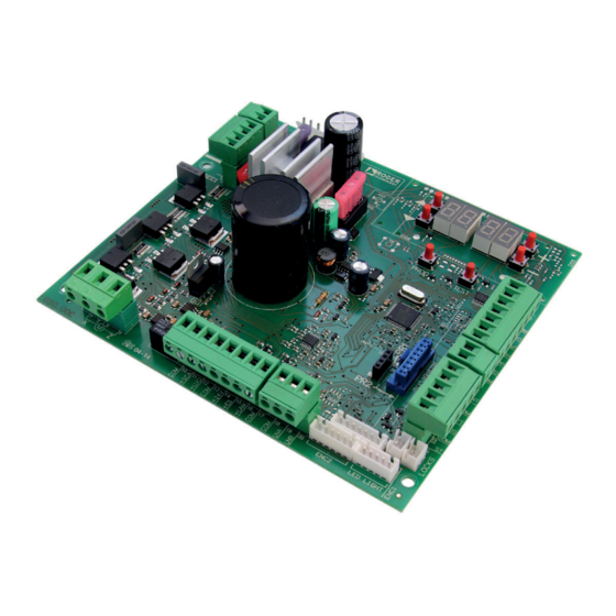
- Page 2 P4.00 Fusibile 3A Connettore scheda carica Fusibile 4A Fuse 3A batterie Fuse 4A Plug for battery charger Display a 4 cifre e 6 tasti di programmazione 4 digit display and 6 Collegamento batterie programming buttons Batteries connection Microprocessore Ingresso alimentazione (secondario trasformatore) Power supply unit Morsettiere dei...
- Page 3 AGILIK • KB PRIMARIO TRASFORMATORE MONOFASE FUSIBILE CEI 61558-2-6 SECONDARIO FUSE 230 Vac 115 Vac (CTRL/115) FUSIBILE FUSE 10A FUSIBILE FUSE 3A FUSIBILE +LUCI FUSE 4A +24V +LAM H93/RX22A/I RICEVITORE RADIO RADIO RECEIVER ENC1 23 24 25 28 29 30 31...
- Page 4 BIONIK Blu/Blue Nero/Black FUSIBILE FUSIBILE FUSIBILE FUSE FUSE FUSE BATTERY CHARGER BATTERY SEC2 PROG TEST SEC1 FUSIBILE H93/RX22A/I FUSE RICEVITORE RADIO RADIO RECEIVER MOTOR 230 Vac 115 Vac X Y Z (CTRL/115) BI/BLED...
- Page 5 Spia stato barriera / Position barrier light 24Vdc 3W marrone/rosso +LUCI Luci asta / Boom arm lights brown/red 24Vdc 12W blue/black blue/black +24V Elettroblocco / Electric lock 12Vdc 10W ( rosso/red +LAM Lampeggiante / Flashing light nero/black 24Vdc 5W Collegamento seriale RS485 RS485 serial connection ENC1 23 24 25...
- Page 6 COLLEGAMENTO CON 1 COPPIA FOTOCELLULE SINCRONIZZABILI CONNECTION WITH 1 PAIR OF SYNCHRONOUS PHOTOCELLS MASTER 1 2 3 4 5 1 2 3 11 12 13 14 ENC2 LED LIGHT USO RACCOMANDATO per fotocellule Serie F4ES - F4S RECOMMENDED USE for COLLEGAMENTO CON 2 COPPIE FOTOCELLULE SINCRONIZZABILI Series F4ES - F4S photocells CONNECTION WITH 2 PAIRS OF SYNCHRONOUS PHOTOCELLS...
- Page 7 TEST FOTOCELLULE · PHOTOCELLS TEST ( COLLEGAMENTO CON 1 COPPIA FOTOCELLULE SINCRONIZZABILI CONNECTION WITH 1 PAIR OF SYNCHRONOUS PHOTOCELLS MASTER 1 2 3 1 2 3 4 5 11 12 13 14 15 ENC2 LED LIGHT USO RACCOMANDATO per fotocellule Serie F4ES - F4S RECOMMENDED USE for COLLEGAMENTO CON 2 COPPIE FOTOCELLULE SINCRONIZZABILI Series F4ES - F4S photocells...
- Page 8 BATTERY SAVING ( BATTERY SAVING + TEST FOTOCELLULE · PHOTOCELLS TEST ( COLLEGAMENTO CON 1 COPPIA FOTOCELLULE SINCRONIZZABILI CONNECTION WITH 1 PAIR OF SYNCHRONOUS PHOTOCELLS MASTER 1 2 3 1 2 3 4 5 USO RACCOMANDATO per 14 15 ENC2 LED LIGHT fotocellule Serie F4ES - F4S RECOMMENDED USE for...
- Page 9 G90/F4ES T90/F4S G90/F4ES G90/F4ES T90/F4S T90/F4S TRIX100 G90/F4ES L'immagine della barriera ha scopo puramente indicativo. The image of the barrier is for reference only.
- Page 10 CONNESSIONE CON ACS/BA/60 CONNECTION WITH ACS/BA/60 verde green ENC2 LED LIGHT verde green Utilizzo alternativo dell'uscita SC (par. diverso da 00). Alternative use of SC output (par. different from 00). ENC2 LED LIGHT C H IU S O ENC2 LED LIG C L O S E D Relay 24V A P E R T O...
- Page 11 AGILIK • KB • BIONIK4HP • BIONIK6 • BIONIK8 Microinterruttore sblocco Unlock microswitch LIGHT BIONIK4 LOCKS Microinterruttore sblocco Unlock microswitch...
- Page 12 AGILIK • KB • BIONIK4HP • BIONIK6 • BIONIK8 ENC1 ENC2 LED LIGHT ENC2 6 FILI 7 FILI 6 WIRES 7 WIRES ENC2 ENC1...
- Page 13 BIONIK4 ENC1 ENC2 LED LIGHT ENC2 ENC2 6 FILI 6 WIRES ENC1 7 FILI 7 WIRES...
- Page 14 AGILIK • KB AG/BLED B73/EXP AG/BLED B73/EXP ENC2 LED LIGHT 100 mm B73/EXP Bi-adesivo Double-sided adhesive...
- Page 15 BIONIK4 • BIONIK4HP • BIONIK6 • BIONIK8 BI/BLED B73/EXP BI/BLED BI/BLED6 BI/BLED8 LED LIGHT B73/EXP ENC2 LED LIGHT B73/EXP 100 mm Bi-adesivo Double-sided adhesive...
- Page 16 AGILIK • KB MESSA A TERRA GROUNDING SCHEME...
- Page 17 BIONIK4 • BIONIK4HP • BIONIK6 • BIONIK8 MESSA A TERRA GROUNDING SCHEME...
- Page 18 BATTERY (+) BLACK BATTERY (-) SEC2 BI/BAT/KIT BATTERY CHARGER AG/BAT/KIT BATTERY CHARGER BATTERY (+) BATTERY (-) PROG TEST SEC2 SEC1 CTRL 11 12 13 14 15 ENC2 LED LIGHT BLACK FUSE T10A 5x20 2 x 12V 4,5Ah AGM Battery ONLY...
- Page 19 BIONIK4 • BIONIK4HP • BIONIK6 • BIONIK8 BATTERY C BATTERY (+) BATTERY (-) BLACK Rosso Nero Black SEC2 Blue BI/BAT/KIT BI/BCHP 2 x 12V 4500 mAh AGM Battery ONLY...
- Page 20 COLLEGAMENTO BARRIERA IN MASTER/SLAVE VIA BUS MASTER/SLAVE BARRIER CONNECTION VIA BUS MASTER Orologio / Timer Apertura / Opening Chiusura / Closing Passo passo / Step by step Apertura parziale / Partial opening Antenna RG58 max 10 m Costa di sicurezza MASTER / MASTER Safety edge STOP (MASTER+SLAVE) 11 12 13 14 15...
- Page 21 SELEZIONE POSIZIONE DI INSTALLAZIONE BARRIERA - PAR. SELECTION OF THE BARRIER INSTALLATION POSITION - PAR. ATTENZIONE: POSIZIONARSI SEMPRE DI FRONTE ALL' ARMADIO DELLA BARRIERA DAL LATO DELLA PORTA DI ISPEZIONE ATTENTION: STAY ALWAYS IN FRONT OF THE BARRIER CABINET FROM THE SIDE OF THE INSPECTION DOOR PARAMETRIZZAZIONE DELLA POSIZIONE DELL' INSTALLAZIONE DELLA BARRIERA CON POSIZIONAMENTO DELL' ARMADIO A SINISTRA E VARCO PASSAGGIO DELL' ASTA A DESTRA...
- Page 22 ROGER TECHNOLOGY is not liable for failure to observe the good practices in during use. The safety devices (photocells, sensing edges, emergency stops, etc.) must be in force, the good practices criteria, the installation environment, the operating logic of the system and the forces generated by the motorised door or gate.
- Page 23 The installer is required to measure impact forces and select on the control unit the appropriate speed and torque values to ensure that the door or gate ROGER TECHNOLOGY cannot be held responsible for any damage or injury caused by the installation of incompatible components which compromise the safety and correct operation of the device.
- Page 24 These instructions must be kept and must be made available to any other persons authorised to use the installation. Declaration CE of Conformity The undersigned Dino Florian, legal representative of Roger Technology - Via Botticelli 8, 31021 Mogliano V.to (TV) DECLARES that the CTRL – 2014/35/EU LVD Standard –...
- Page 25 22. Product description The CTRL controller is a unit for the sensored control of the ROGER brushless motor powering an electromechanical barrier. The CTRL uses two magnetic encoders, with one monitoring the motor and another monitoring the position of the boom, even when it is moved manually.
- Page 26 Updates of version P4.00 1. Added a selection to par. 2. Added a selection to par. 3. Improved phototest management. 4. Improved management of guaranteed closure. 5. Expanded the memory from 64k to 256k of FLASH in view of future developments. Technical characteristics of product AG/004 AG/004/115...
- Page 27 Description of connections To access the control unit. remove the barrier head. Figure 1-2-3 shows connection diagrams. Typical installation Recommended cable Power supply H07RN-F 3x1,5 mm double insulated cable Photocell - Receiver F4ES/F4S Cable 5x0,5 mm (max 20 m) Photocell - Transmitter F4ES/F4S Cable 3x0,5 mm (max 20 m) Key selector R85/60...
- Page 28 [B] (not supplied). DESCRIPTION Connection to mains power, 230 Vac ±10% (115 Vac ±10% 60 Hz). - 230 Vac ± 10% for CTRL control panel. - 115 Vac ± 10% for CTRL/115 control panel. Fuse 5x20 T1A.
- Page 29 Commands and Accessories If not installed, safety devices with NC contacts must be jumpered at the COM terminals, or disabled by modifying the parameters For installations with two opposed barriers, connections for command signals and accessories must be made on the MASTER controller. The sensing edge and, if used, the STOP command signal must be connected to the SLAVE controller.
- Page 30 The current manoeuvre is arrested if the safety contact opens. N.B.: the controller is supplied with this contact already jumpered by ROGER TECHNOLOGY. In the case of installations with two opposed barriers, if the STOP command signal is given for the MASTER barrier, both barriers stop.
- Page 31 CONTACT DESCRIPTION Open command input (NO). 32(AP) 28(COM) 32(AP) 28(COM) The command input (N.C.) available for the connection of the sensor of the ACS/BA/60 detachable When the ACS/BA/60 detachable boom safety system intervenes, the contact switches from N.C. to N.O. Enable the contact via parameter 33(ORO) 34(COM)
- Page 32 Function buttons and display BUTTON DESCRIPTION Next parameter Previous parameter DOWN Increase value of parameter by 1 DOWN Decrease value of parameter by 1 PROG Travel acquisition TEST Activate TEST mode PROG TEST • Press the UP and/or DOWN buttons to view the parameter you intend to modify. •...
- Page 33 10.2 Command and safety device status display mode COMMAND STATUS SAFETY DEVICE STATUS COMMAND STATUS: The command status indicators on the display (segments AP = open, PP = step mode, CH = close, PED = partial opening, ORO=clock) are BREAK a step mode command is received, the segment PP illuminates).
- Page 34 Travel acquisition For the system to function correctly, the barrier travel must be acquired by the controller. 11.1 Before starting: IMPORTANT: Select the length of the boom with the parameter It is very important that this parameter is selected correctly. An incorrect setting may cause severe damage or injury.
- Page 35 IMPORTANT! Lubricate the pivot points with lithium based grease (EP LITIO) OPEN CLOSE 2. Check that the "operator present" function is not enabled ( 3. Check the spring balance setting and the mechanical stop settings. For further information, refer to the installation manual of the barrier. >45°...
- Page 36 • Unlock the barrier. AGILIK-KB-BIONIK4HP-BIONIK6-BIONIK8. Turn the key anticlockwise by two full turns. BIONIK4. Open the release cover. • The barrier goes to 45° degree. • After a few seconds, the message is shown on the display. The controller unit launches a calibration procedure. The operating parameters of the motor are determined during calibration.
- Page 37 If the installation position is changed from the right to the left, the position of the spring(s) must also be changed. 6. MASTER UNLOCK LOCK 2x360° 2x360° 45° PROG AP P- PH A5 PH A5 x4 s BIONIK 4HP, 6, BIONIK 4HP, 6, 8, PC, PE ONLY FOR BI/004...
- Page 38 • If the motor calibration procedure is successful, the message • To lock the barrier again AGILIK-KB-BIONIK4HP-BIONIK6-BIONIK8. Turn the key clockwise by two full turns. BIONIK4. Close the release cover and turn the key. • The acquisition procedure now starts. The message is shown on the display and the barrier starts opening at low speed.
-
Page 39: Table Of Contents
Index of parameters FACTORY PARAM. DESCRIPTION PAGE DEFAULT Enable RS485 serial communication (MASTER-SLAVE) Barrier model and the length of the boom selection Automatic closing after time pause (from barrier completely open position) Automatic closing after mains power outage Step mode control function selection (PP) Condominium function for partial open command (PED) Enable "operator present"... -
Page 40: Param
FACTORY PARAM. DESCRIPTION PAGE DEFAULT Operating mode of signal lights on boom Enable safeguarded barrier closure Safeguarded closure activation time setting Parking access mode selection Enable close command after photocell activation (FT) Selection of the battery operation management Selection of the battery operation limitations Selection of the battery type and consumption reduction Restoring factory default values HW version... -
Page 41: Enable Rs485 Serial Communication (Master-Slave)
Parameters menu PARAMETER PARAMETER VALUE Enable RS485 serial communication (MASTER-SLAVE) Enabling serial communication permits the synchronised control of two opposing automation systems. Example system. Disabled. SLAVE automation system. MASTER automation system. When the MASTER automation is enabled, the message illuminates on the display for a few seconds. If the SLAVE automation system is detected correctly, C485 illuminates. -
Page 42: Step Mode Control Function Selection (Pp)
Step mode control function selection (PP) Open-stop-close-stop-open-stop-close... The automatic closing timer restarts if a new step mode command is received with the boom in the completely open position. Step mode commands are ignored while the barrier is opening. This allows the boom to open completely and prevents unintentional closing. -
Page 43: Setting Deceleration During Closure
Setting deceleration during closure 01= barrier decelerates near stop ... 10= barrier decelerates long before reaching the stop. N.B.: Available values may be limited by the setting for parameter Connect the shatter-proof system sensor to one of the control inputs on the control unit. When the shatter-proof system is triggered, the signal switches from N.C. -
Page 44: Obstacle Detection Time Setting (Crush Prevention)
Normally not powered. The electric lock is powered for 1,5 s at the start of the opening manoeuvre to allow the barrier to open. Magnetic "ventouse" electric lock normally powered when the barrier is completely closed. Not powered when the barrier is moving or completely open Obstacle detection function setting (crush prevention) The barrier reopens if the obstacle detection system is activated during a closing manoeuvre. -
Page 45: Photocell (Ft) Mode With Barrier Closed
TEMPORARY STOP. The barrier stops and remains stationary as long as the photocell is obstructed. The barrier resumes closing when the photocell is cleared. DELAYED REVERSE. The barrier stops if the photocell is obstructed. The barrier opens when the photocell is cleared. - Page 46 quency when the boom is near the mechanical stops. Operating mode of signal lights on boom N.B.: to reduce power consumption, the controller automatically sets this par. to during battery pow- ered operation. Disabled. Lights always off. Lights always on. When the clock function is active, the barrier opens and remains open.
- Page 47 Directional mode 2. When entering, the barrier is opened with an AP open command, and closes after the automatic closing time set with parameter different to NOTE When leaving the parking area, the barrier is opened by a PED command received from the magnetic loop. Once the vehicle has crossed the barrier and released contact FT (NC), the barrier closes.
- Page 48 N.B. HW version Year of manufacture Week of manufacture Serial number FW version RS485 serial communication version View manoeuvre counter The number consists of the values of the parameters from multiplied by 100. N.B. Manoeuvres performed x100 = 1,234,500 manoeuvres View manoeuvre hour counter The number consists of the values of the parameters from N.B.
- Page 49 Examples of applications in parking access mode The CTRL controller manages the system in parking access mode. The function is enabled through the parameter and ONLY the AP and/or PED command inputs at the terminal board must be used. N.B.: the input FT cannot be disabled in the following operating situations. If the contact (NC) is opened during a closing manoeuvre, the barrier reopens and remains open until the contact is closed again.
- Page 50 Safety input and command status (TEST mode) DISPLAY POSSIBLE CAUSE ACTION BY SOFTWARE PHYSICAL CORRECTIVE ACTION MASTER barrier not moving. STOP Check STOP button/contact on MAS- contact of MASTER barrier open TER controller. (rS) (message visible for SLAVE barrier). Install a STOP button (NC) or jumper the ST contact with the COM contact of the MASTER controller.
- Page 51 Alarms and faults PROBLEM ALARM SIGNAL POSSIBLE CAUSE CORRECTIVE ACTION POWER LED off No power. Check power cable. POWER LED off Fuses blown. Replace fuse. Always disconnect from mains power before remov- Fuse F1 blown or damaged. Replace fuse. This message is not visible if Always disconnect from mains power before remov- controller is in battery power mode.
- Page 52 PROBLEM ALARM SIGNAL POSSIBLE CAUSE CORRECTIVE ACTION AGILIK-KB-BI/004HP-BI/006-BI/008 ing the key two complete turns clockwise. Release device open. BIONIK4 key. Open barrier inspection hatch Close the inspection hatch correctly and check the (if the emergency stop micro- micro-switch connection. switch is installed). LOCKS connectors incorrectly Check the connector connections.
- Page 53 PROBLEM ALARM SIGNAL POSSIBLE CAUSE CORRECTIVE ACTION Motor calibration failed. Repeat acquisition procedure. If the problem persists, check the cable connecting encoder 1 to the motor. Check that the motor turns without impediment. Acquisition proce- Contact technical support in case of any problems. dure does not com- plete correctly.
- Page 54 INFO MODE x5 s 1 click INFO mode may be used to view certain parameters measured by the CTRL controller. Press and hold the TEST button for 5 seconds from the “View command signals and safety devices” mode with the Parameter...
Need help?
Do you have a question about the CTRL and is the answer not in the manual?
Questions and answers