Table of Contents
Advertisement
Quick Links
PONOVO POWER CO., LTD
No. 139 Jinghai Third Road, BDA, Beijing, China, 100176
Office
TEL. +86 (10) 59089666
E-Mail
Info@relaytest.com
Website
www.relaytest.com / www.ponovo.com.cn
VERSION:
DATE:
This manual is the publication of PONOVO POWER CO.,LTD. Any form of copy should
obtain the consent of it.
The manual represents the technology status at publication time. The product information,
directions and all technical specifications do not have contract binding. The company
subjects to changing the technical and configuration information without notice. The
company is not responsible for possible errors occurred in the manual.
PAV120Bi
POWER AMPLIFIER USER MANUAL
PAV120Bi-AE-1.50
MARCH 2021
1
Advertisement
Table of Contents

Related Manuals for Ponovo PAV120Bi


Summary of Contents for Ponovo PAV120Bi
- Page 1 PAV120Bi-AE-1.50 DATE: MARCH 2021 This manual is the publication of PONOVO POWER CO.,LTD. Any form of copy should obtain the consent of it. The manual represents the technology status at publication time. The product information, directions and all technical specifications do not have contract binding. The company subjects to changing the technical and configuration information without notice.
-
Page 2: Table Of Contents
PAV120Bi Power Amplifier User Manual Content 1. Safety Precaution ........................... 3 2. General ............................9 3. Main Technical Specifications ..................... 10 3.1 Power Supply ........................10 3.2 Use Environment ....................... 10 3.3 Dimension and Weight ...................... 11 3.4 Voltage Amplifier ........................ 11 4. -
Page 3: Safety Precaution
PAV120Bi Power Amplifier User Manual 1. Safety Precaution Read User Manual before operation. 1. Check carefully all buttons are positioned correctly before startup. 1) Pause button in correct position in pressed state. 2) ON/OFF in OFF state. 3) Not press high power button (High power indicator in OFF state) 2. - Page 4 PAV120Bi Power Amplifier User Manual vapor. 14. The 500V dangerous voltage can be in the equipment and please don’t remove the cover by yourself 15. Please contact the manufacture for any maintenance 16. The guarantee will become invalid if kit is opened by the customer.
- Page 5 PAV120Bi Power Amplifier User Manual For Your Safety Please Note This symbol indicates potential hazards by electrical voltages/currents caused by, for example, wrong connections, short-circuits, technically inadequate or faulty equipment or by disregarding the safety notes of the following sections.
- Page 6 PAV120Bi Power Amplifier User Manual Do not Move or Maintain the Instrument When it is Powered On To avoid personnel injuries, any position adjustment, maintenance or parts replacement are forbidden when instrument is on. Use Proper Fuse Please use the specified fuses.
- Page 7 PAV120Bi Power Amplifier User Manual Keep Product Surfaces Clean and Dry To avoid the influence of dust and/or moisture in air, please keep the surface of device clean and dry. Operate the Instrument in a Suitable Environment The best condition for optimal measurement is: 5 ℃ to 40℃; less than 2 ℃/hour changing, 20% to 80% RH and the instrument should not be placed towards the air outlet.
- Page 8 PAV120Bi Power Amplifier User Manual NOTE: This equipment has been tested and found to comply with the limits for a Class A digital device, pursuant to Part 15 of the FCC Rules. These limits are designed to provide reasonable protection against harmful interference when the equipment is operated in a commercial environment.
-
Page 9: General
DC offset, drift, transient response, load driving capability aspects, which are very difficult to fix. PAV120Bi is specially designed for R&D of power system simulation. It is adapt to various capacitive and inductive load. There are 6-phase voltage outputs with max. 120VRms per... -
Page 10: Main Technical Specifications
PAV120Bi Power Amplifier User Manual 3. Main Technical Specifications 3.1 Power Supply 3-phase 380V AC Power supply 50/60Hz Power capacity 750VA 3.2 Use Environment Operating temperature: 25 deg±10 deg Storage Temperature: -25 deg—+70 deg Related humidity: 20%RH—85%RH Pressure: 86 kPa—106kPa... -
Page 11: Dimension And Weight
PAV120Bi Power Amplifier User Manual 3.3 Dimension and Weight Dimension: 4U Weight:20kg 3.4 Voltage Amplifier 6x0~120V RMS Voltage output >60VA (120V output) Max. output power Standard: 0~7.07V RMS (±10Vpek), Gain: 20V/V Input signal-Analog, Gain Option: 0~14.14V RMS (±20Vpek), Gain: 10V/V... -
Page 12: Functions And Features
PAV120Bi Power Amplifier User Manual 4. Functions and Features 4.1 Basic Principle PAV120Bi consists of the below parts mainly: 1) High-speed differential input circuit for amplifier; 2) High-performance voltage power amplifier module; 3) Distortion detection and alarm circuit. Each amplifier has the overload or output distortion detection circuit. -
Page 13: Functions
PAV120Bi Power Amplifier User Manual 4.2 Functions 1) The differential input circuit can reduce the influence of the common mode noise to make it possible that use long wires to connect across the amplifier and signal source, which will reduce mutual effects between all amplifiers during output to guarantee the operation safety of the simulator. -
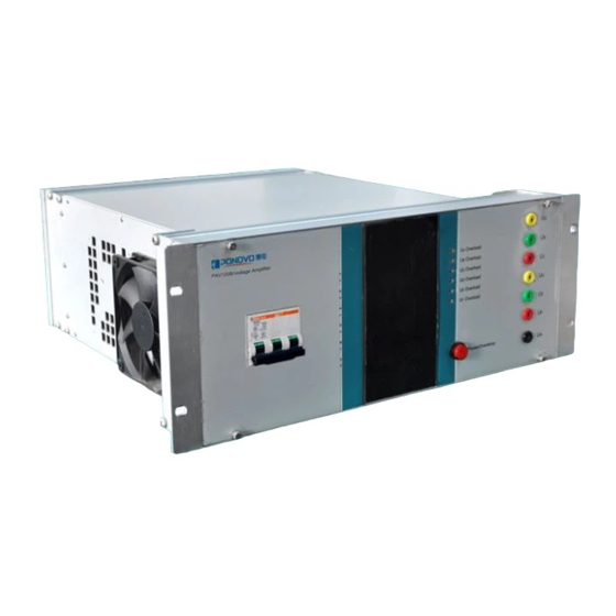
Page 14: Panels
PAV120Bi Power Amplifier User Manual 5. Panels 5.1 Front Panel 1. Switch: Power On/Off 2. Display: Show the voltage value 3. Overload indicators: Each indicator is related to each output. 4. Pause/Overtemp indicator/button: Press it for pause the output and light on; Or overtemperature light on. -
Page 15: Rear Panel
PAV120Bi Power Amplifier User Manual 5.2 Rear Panel 6. Power: Power supply socket * . Voltage Output: It is connected with the voltage input of the test object 8. Gain: There are two options for choice and the related indicators for Gain will be on in front and rear panels. - Page 16 PAV120Bi Power Amplifier User Manual **: Ud out: Normal: It outputs normally based on the input signal. 3U0: It outputs zero sequence voltage based on the UA+UB+UC calculation result. ***: LPF: Low-pass filter. A low-pass filter (LPF) is a filter that passes signals with a frequency lower than a selected cutoff frequency and attenuates signals with frequencies higher than the cutoff frequency.
-
Page 17: Terminal Definition
PAV120Bi Power Amplifier User Manual 5.3 Terminal definition Voltage Signal Input Channel Function signal signal UB signal UB signal UC signal UC signal Definition input + input - input + input - input + input - Channel Function signal signal... -
Page 18: How To Use Amplifier
PAV120Bi Power Amplifier User Manual 6. How to Use Amplifier 6.1 Wiring The amplifier voltage input signal terminals should be connected with the simulation system’s D/A output signal correctly. Please refer to the Terminal Definition for detail. Pay attention that the shielded layer at simulation system should be grounded. -
Page 19: Voltage Output Display
PAV120Bi Power Amplifier User Manual respectively, and then inactivate the pause function and input the simulation signal, the amplifier will enter into simulation status. 6.3.2 Voltage Output Display Voltage output will be display in real time on the front panel. -
Page 20: Amplifier Inspection
PAV120Bi Power Amplifier User Manual 7. Amplifier Inspection All amplifiers have passed strict tests and high power output running test before delivery. The test items include function test, linearity, load stability, total harmonic distortion, maximum output power, amplitude and frequency characteristic, input/output delay, step response, system phase precision tests. -
Page 21: Cables
PAV120Bi Power Amplifier User Manual 8. Cables Colour coded voltage cables SAW0202 colour coded voltage cable 8 pieces Amount: The voltage cables to connect the amplifier output to other safety sockets of, generally the voltage parts. -
Page 22: Pap-02B Standard Chassis And Power Control Device
PAV120Bi Power Amplifier User Manual 9. PAP-02B Standard Chassis and Power Control Device User can order suitable chassis and chassis power based on their needs. Related parameters are shown as follow: 9.1 Standard Chassis Dimension (W*D*H) 600*800*1800mm Weight 50kg Maximum load: 300kg 9.2 PAP-02B Power Control Device... -
Page 23: Operation
PAV120Bi Power Amplifier User Manual 9.3 Operation Before power on the PAP02, please carefully check if the power on each amplifier is turned off. 1) Turn on the power of PAP02 first 2) Turn on the individual amplifier power in testing.
Need help?
Do you have a question about the PAV120Bi and is the answer not in the manual?
Questions and answers