Table of Contents
Advertisement
Quick Links
PONOVO POWER CO., LTD
No. 139 Jinghai Third Road, BDA, Beijing, China, 100176
Office
TEL. +86 (10) 59089666
E-Mail
Info@relaytest.com
Website
www.relaytest.com / www.ponovo.com.cn
VERSION:
DATE:
This manual is the publication of PONOVO POWER CO.,LTD. Any form of copy should
obtain the consent of it.
The manual represents the technology status at publication time. The product information,
directions and all technical specifications do not have contract binding. The company
subjects to changing the technical and configuration information without notice. The
company is not responsible for possible errors occurred in the manual.
PAV250Bi
POWER AMPLIFIER USER MANUAL
PAV250Bi-AE-1.50
MARCH 2021
1
Advertisement
Table of Contents

Related Manuals for Ponovo PAV250Bi


Summary of Contents for Ponovo PAV250Bi
- Page 1 PAV250Bi-AE-1.50 DATE: MARCH 2021 This manual is the publication of PONOVO POWER CO.,LTD. Any form of copy should obtain the consent of it. The manual represents the technology status at publication time. The product information, directions and all technical specifications do not have contract binding. The company subjects to changing the technical and configuration information without notice.
-
Page 2: Table Of Contents
PAV250Bi Power Amplifier User Manual Content 1. Safety Precaution.........................3 2. General Description ......................9 3. Main Technical Specifications ....................10 3.1 Power Supply ......................10 3.2 Use Environment ......................10 3.3 Dimension and Weight .....................11 3.4 Technical Specifications...................11 3.5 Digital Display of Voltage Output ................12 4. -
Page 3: Safety Precaution
PAV250Bi Power Amplifier User Manual 1. Safety Precaution Read User Manual before operation. 1. Check carefully all buttons are positioned correctly before startup. 1) Pause button in correct position in pressed state. 2) ON/OFF in OFF state. 3) Not press high power button (High power indicator in OFF state) 2. - Page 4 PAV250Bi Power Amplifier User Manual 12. Avoid the equipment to be wet by rain 13. Do not switch-on and operate the equipment in the place having explosive gas or water vapor. 14. The 500V dangerous voltage can be in the equipment and please don’t remove the cover by yourself 15.
- Page 5 PAV250Bi Power Amplifier User Manual For Your Safety Please Note This symbol indicates potential hazards by electrical voltages/currents caused by, for example, wrong connections, short-circuits, technically inadequate or faulty equipment or by disregarding the safety notes of the following sections.
- Page 6 PAV250Bi Power Amplifier User Manual Do not Move or Maintain the Instrument When it is Powered On To avoid personnel injuries, any position adjustment, maintenance or parts replacement are forbidden when instrument is on. Use Proper Fuse Please use the specified fuses.
- Page 7 PAV250Bi Power Amplifier User Manual Keep Product Surfaces Clean and Dry To avoid the influence of dust and/or moisture in air, please keep the surface of device clean and dry. Operate the Instrument in a Suitable Environment The best condition for optimal measurement is: 5 ℃ to 40℃; less than 2 ℃/hour changing, 20% to 80% RH and the instrument should not be placed towards the air outlet.
- Page 8 PAV250Bi Power Amplifier User Manual digital device, pursuant to Part 15 of the FCC Rules. These limits are designed to provide reasonable protection against harmful interference when the equipment is operated in a commercial environment. This equipment generates, uses, and can radiate radio frequency energy and, if not installed and used in accordance with the instruction manual, may cause harmful interference to radio communications.
-
Page 9: General Description
DC offset, drift, transient response, load driving capability aspects, which are very difficult to fix. PAV250Bi is specially designed for R&D of power system simulation. It is adapt to various capacitive and inductive load. There are 6-phase voltage outputs with max. 250V rms per... -
Page 10: Main Technical Specifications
PAV250Bi Power Amplifier User Manual 3. Main Technical Specifications 3.1 Power Supply Power supply 3 phase 380V AC 50/60Hz Power capacity 750VA 3.2 Use Environment Operating temperature: 25 deg±10 deg Storage Temperature: -25 deg—+70 deg Related humidity: 20%RH—85%RH Pressure: 86 kPa—106kPa... -
Page 11: Dimension And Weight
PAV250Bi Power Amplifier User Manual 3.3 Dimension and Weight Dimension: 4U Weight:20kg 3.4 Technical Specifications Voltage output 6x0~250V RMS Max. output power >75VA (250V output) Standard: 0~7.07V RMS (±10Vpek), Gain: 40V/V Input signal-Analog, Gain Option: 0~11.31V RMS (±16Vpek), Gain: 24V/V... -
Page 12: Digital Display Of Voltage Output
PAV250Bi Power Amplifier User Manual 3.5 Digital Display of Voltage Output The RMS of voltage output can be displayed in real-time on the panel. -
Page 13: Functions And Features
PAV250Bi Power Amplifier User Manual 4. Functions and Features 4.1 Basic Principle PAV250Bi consists of the below parts mainly: 1) High-speed differential input circuit for amplifier; 2) High-performance voltage power amplifier module; 3) Distortion detection and alarm circuit. Each amplifier has the overload or output distortion detection circuit. -
Page 14: High Voltage Output
PAV250Bi Power Amplifier User Manual 2) The output voltage distortion and overload auto-detection circuit will protect the voltage amplifier output overload or short-circuit automatically. It automatically closes amplifier input/output, and the overload alarm in rear panel lights. After overload and short-circuit disappear, it restores to working status. -
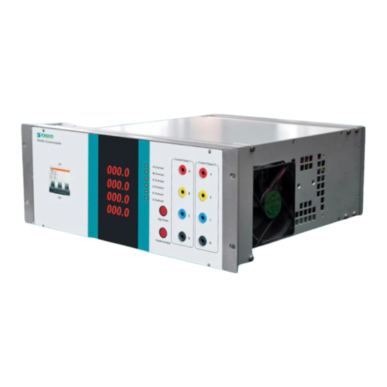
Page 15: Panels
PAV250Bi Power Amplifier User Manual 5. Panels 5.1 Front Panel 1. Power Switch: Power on/off 2. Display: Show the current/ voltage value (The current output is showing on above picture.) 3. Indicator: The working status will be showing. 4. High power button: Switch the voltage between 0~120V and 0~250V 5. -
Page 16: Rear Panel
PAV250Bi Power Amplifier User Manual 5.2 Rear Panel 8. Power socket: Please use the power cable supplied by PONOVO (The cable with special port must be used). 9 Earth ground: It should be grounded with earth during testing. * . Voltage output: It is connected with the voltage input of the test object. -
Page 17: Terminal Definition
PAV250Bi Power Amplifier User Manual 5.3 Terminal Definition Contact Signal Output Terminal No. Output Mode Voltage output Function Overheat alarm Pause signal overload/short-circuit Reserved Definition signal output output alarm signal Control Signal Input Terminal No. Output Mode COM- Function Pause control +12V... - Page 18 PAV250Bi Power Amplifier User Manual Voltage Signal Input Terminal No. Channel Function VA signal VA signal VB signal VB signal VC signal VC signal Definition input + input - input + input - input + input - Terminal No. Channel...
-
Page 19: How To Use Amplifier
PAV250Bi Power Amplifier User Manual 6. How to Use Amplifier 6.1 Wiring The amplifier current/ voltage input signal terminals should be connected with the simulation system’s D/A output signal correctly. Please refer to the Terminal Definition for detail. Pay attention that the shielded layer at simulation system should be grounded. -
Page 20: High Power
PAV250Bi Power Amplifier User Manual 6.3.2 High Power Note: 1. Generally don’t’ press high power button (The high power indicator is off.). 2. Never operate live signal and load cables with voltage output to protect the safety of equipment and personnel. -
Page 21: Amplifier Inspection
PAV250Bi Power Amplifier User Manual 7. Amplifier Inspection All amplifiers have passed strict tests and high power output running test before delivery. The test items include function test, linearity, load stability, total harmonic distortion, maximum output power, amplitude and frequency characteristic, input/output delay, step response, system phase precision tests. -
Page 22: Cables
PAV250Bi Power Amplifier User Manual 8. Cables Colour coded voltage cables SAW0202 colour coded voltage cable 8 pieces Amount: The voltage cables to connect the amplifier output to other safety sockets of, generally the voltage parts. -
Page 23: Pap-02B Standard Chassis And Power Control Device
PAV250Bi Power Amplifier User Manual 9. PAP-02B Standard Chassis and Power Control Device User can order suitable chassis and chassis power based on their needs. Related parameters are shown as follow: 9.1 Standard Chassis Dimension (W*D*H) 600*800*1800mm Weight 50kg Maximum load: 300kg 9.2 PAP-02B Power Control Device... -
Page 24: Operation
PAV250Bi Power Amplifier User Manual 9.3 Operation Before power on the PAP02, please carefully check if the power on each amplifier is turned off. 1) Turn on the power of PAP02 first 2) Turn on the individual amplifier power in testing.
Need help?
Do you have a question about the PAV250Bi and is the answer not in the manual?
Questions and answers