Table of Contents
Advertisement
Quick Links
PONOVO POWER CO., LTD
No. 139 Jinghai Third Road, BDA, Beijing, China, 100176
Office
TEL. +86 (10) 59089666
E-Mail
Info@relaytest.com
Website
www.relaytest.com / www.ponovo.com.cn
VERSION:
DATE:
This manual is the publication of PONOVO POWER CO.,LTD. Any form of copy should obtain the
consent of it.
The manual represents the technology status at publication time. The product information,
directions and all technical specifications do not have contract binding. The company subjects to
changing the technical and configuration information without notice. The company is not
responsible for possible errors occurred in the manual.
PAC60Bi (PAC60Ci)/PAV120Bi POWER AMPLIFIER USER MANUL
PAC60Bi (PAC60Ci)/ PAV120Bi
POWER AMPLIFIER USER MANUAL
PAC60Bi (PAC60Ci)/ PAV120Bi-AE-1.10
16/01/2017
Advertisement
Table of Contents

Related Manuals for Ponovo PAC60Bi


Summary of Contents for Ponovo PAC60Bi
- Page 1 PAC60Bi (PAC60Ci)/ PAV120Bi-AE-1.10 DATE: 16/01/2017 This manual is the publication of PONOVO POWER CO.,LTD. Any form of copy should obtain the consent of it. The manual represents the technology status at publication time. The product information, directions and all technical specifications do not have contract binding. The company subjects to changing the technical and configuration information without notice.
- Page 2 PAC60Bi (PAC60Ci)/PAV120Bi POWER AMPLIFIER USER MANUAL Specifications and typical configurations Panel mount type Model Description Output Type Notes PAC60Bi Amplifier 3×60A RMS 800VA/phase 3 phase 380VAC±10%, 47-63Hz PAC60Ci Amplifier 6×30A RMS 450VA/phase 3 phase 380VAC±10%, 47-63Hz PAV120Bi Amplifier 6 x 120v RMS 60VA/phase 3 phase 380VAC±10%,...
- Page 3 PAC60Bi (PAC60Ci)/PAV120Bi POWER AMPLIFIER USER MANUAL PRECAUTION Read User Manual before operation. Check carefully all buttons are positioned correctly before startup. Position high power button correctly. Position power switch correctly. Before running the test, all the inputs of amplifier system and all the signal outputs of RTDS must be checked.
-
Page 4: Table Of Contents
1.6 PAC60Bi (PAC60Ci) Current Amplifier ................12 1.7 PAV120Bi Voltage Amplifier ..................... 12 1.8 Current/Voltage Amplitude Display .................. 13 2. PAC60Bi (PAC60Ci) Current Power Amplifier ............. 14 2.1 Basic Principle ......................... 14 2.2 Function ........................... 14 2.3 High Power Current Output ..................... 15 2.4 Front and Rear Panels ..................... -
Page 5: Main Technical Performance
PAC60Bi (PAC60Ci)/PAV120Bi POWER AMPLIFIER USER MANUAL 1. Main Technical Performance 1.1 Dimension and Weight 1.1.1 Dimension... - Page 6 PAC60Bi (PAC60Ci)/PAV120Bi POWER AMPLIFIER USER MANUAL 1.1.2 PAC60Ci 1.1.3 PAV120Bi...
- Page 7 PAC60Bi (PAC60Ci)/PAV120Bi POWER AMPLIFIER USER MANUAL 1.1.4 PAD24...
- Page 8 PAC60Bi (PAC60Ci)/PAV120Bi POWER AMPLIFIER USER MANUAL 1.1.5 PSS01B...
- Page 9 PAC60Bi (PAC60Ci)/PAV120Bi POWER AMPLIFIER USER MANUAL 1.1.6 PSS02B or PSS05B...
- Page 10 PAC60Bi (PAC60Ci)/PAV120Bi POWER AMPLIFIER USER MANUAL 1.1.7 PAT01...
-
Page 11: Weight
PAC60Bi (PAC60Ci)/PAV120Bi POWER AMPLIFIER USER MANUAL 1.2 Weight 1.2.1 PAP02: 82KG 1.2.2 PAC60Bi: 32.5KG or PAC60Ci: 32.5KG PA30Bi 29.5 KG 1.2.3 PAV120Bi: 21.30KG or PAV250Bi: 23KG 1.2.4 PAT01: 6.5KG The total weight differs from the configurations and it is the sum weight of each component. -
Page 12: Pac60Bi (Pac60Ci) Current Amplifier
PAC60Bi (PAC60Ci)/PAV120Bi POWER AMPLIFIER USER MANUAL 1.6 PAC60Bi (PAC60Ci) Current Amplifier Type PAC60Bi PAC60Ci Item Max. Output Current 60A RMS 30A RMS >800VA(60A output) >450VA(30A output) Max. Output Power Input Signal 0 -6 V RMS(±10.6Vp-p) 20KΩ Differential Input Impedance Gain... -
Page 13: Current/Voltage Amplitude Display
PAC60Bi (PAC60Ci)/PAV120Bi POWER AMPLIFIER USER MANUAL 1.8 Current/Voltage Amplitude Display There are 3 and a half digits of true RMS values displayed for output current, voltage with the precision of 1%. -
Page 14: Pac60Bi (Pac60Ci) Current Power Amplifier
PAC60Bi (PAC60Ci)/PAV120Bi POWER AMPLIFIER USER MANUAL 2. PAC60Bi (PAC60Ci) Current Power Amplifier 2.1 Basic Principle This current amplifier is a kind of linear current power amplifier targeting at the CT characteristic of power system, with the strengths of high accuracy, high current and quick response, which consists of below parts mainly: 1) High-speed differential input circuit for amplifier;... -
Page 15: High Power Current Output
PAC60Bi (PAC60Ci)/PAV120Bi POWER AMPLIFIER USER MANUAL 2.3 High Power Current Output With high power control button depressed, after several seconds, the high power control button light will turn on. By then the current amplifier can improve 20% of output power. This button can be used in case there have high current output needed and heavy load applied. -
Page 16: Front And Rear Panels
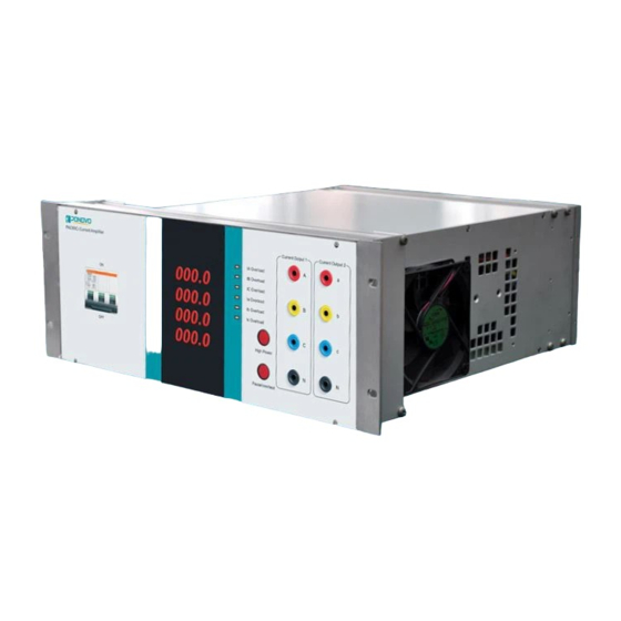
PAC60Bi (PAC60Ci)/PAV120Bi POWER AMPLIFIER USER MANUAL 2.4 Front and Rear Panels PAC60Bi Front and Rear Panels... - Page 17 PAC60Bi (PAC60Ci)/PAV120Bi POWER AMPLIFIER USER MANUAL PAC60Ci Front and Rear Panels...
-
Page 18: Terminal Definition Of Rear Panel
PAC60Bi (PAC60Ci)/PAV120Bi POWER AMPLIFIER USER MANUAL 2.5 Terminal Definition of Rear Panel Contact Signal Output Terminal No. Output Mode Voltage output Overheat Inverse time Function overload/ Pause signal alarm signal limit signal Definition short-circuit output output output alarm signal Control Signal Input... -
Page 19: Pav120Bi Voltage Amplifier
PAC60Bi (PAC60Ci)/PAV120Bi POWER AMPLIFIER USER MANUAL 3. PAV120Bi Voltage Amplifier 3.1 Basic Principle This voltage power amplifier is a linear voltage power amplifier specially targeting at the PT characteristics of power system with the strengths of high accuracy, high voltage and quick response, which consists of below parts mainly: 1) High-speed differential input circuit for amplifier;... - Page 20 PAC60Bi (PAC60Ci)/PAV120Bi POWER AMPLIFIER USER MANUAL “Overheat” alarm light on the front panel will turn on. 5) 3U accumulation function. U and U can be added up to form a 3U signal to be outputted via U channel. 6) Two gain options. User can accord to maximum voltage output value to select right gain.
-
Page 21: Front And Rear Panels
PAC60Bi (PAC60Ci)/PAV120Bi POWER AMPLIFIER USER MANUAL 3.3 Front and Rear Panels... - Page 22 PAC60Bi (PAC60Ci)/PAV120Bi POWER AMPLIFIER USER MANUAL 3.4 Terminal Definition of Rear Panel Terminal 2, 3 9, A, B, C Low pass Test Test Test Pause Function Low pass Pause Filtering signal signal control control Definition filtering - control - +12V...
-
Page 23: Pat01 Timing Output Control And Reference Signal Test Source
PAC60Bi (PAC60Ci)/PAV120Bi POWER AMPLIFIER USER MANUAL 4. PAT01 Timing Output Control and Reference Signal Test Source 4.1 Basic Principle and Function 1. Test signal is a good-stability signal generator connected to all amplifiers together to be feasible to check the amplifier works normally. The input signal amplitude is 0.1/1.0V, which can test the linearity and gain stability of the amplifier. -
Page 24: Pat01 Front And Rear Panels
PAC60Bi (PAC60Ci)/PAV120Bi POWER AMPLIFIER USER MANUAL 4.2 PAT01 Front and Rear Panels PAT01 Front Panel PAT01 Rear Panel... -
Page 25: Terminal Definition
PAC60Bi (PAC60Ci)/PAV120Bi POWER AMPLIFIER USER MANUAL 4.3 Terminal Definition Definition of test signal terminals Terminal Definition Wire No. Wire Color Current amplifier’s rectification White(Blue) signal + of group I Amplifier’s rectification signal- of White(Blue) group I Voltage amplifier’s rectification White(Blue) signal + of group I Amplifier’s rectification control + of... - Page 26 PAC60Bi (PAC60Ci)/PAV120Bi POWER AMPLIFIER USER MANUAL Definition of time limit terminals Terminal Definition Wire No. Wire Color Ia current output’s test signal+ White(Blue) Ia current output’s test signal- White(Blue) Ib current output’s test signal+ White(Blue) Ib current output’s test signal - White(Blue) Ic current output’s test signal+...
-
Page 27: How To Use Amplifier
PAC60Bi (PAC60Ci)/PAV120Bi POWER AMPLIFIER USER MANUAL 5. How to Use Amplifier 5.1 Wiring Connect digital simulator system’s D/A output signals to corresponding input terminals for voltage/current of the amplifier (Refer to the panel diagram for detail). Pay attention that the shielded layer of its signal wire at the simulator system side should be grounded. -
Page 28: Amplifier Off
PAC60Bi (PAC60Ci)/PAV120Bi POWER AMPLIFIER USER MANUAL 5.4 Amplifier Off If you want to turn off the amplifier, please terminate the simulator signal input, pull off all wires between amplifier and loads, and turn off the power in a row. -
Page 29: Amplifier Test
PAC60Bi (PAC60Ci)/PAV120Bi POWER AMPLIFIER USER MANUAL 6. Amplifier Test All amplifiers have passed strict tests and high power output running test before delivery. The test items include function test, linearity, load stability, total harmonic distortion, maximum output power, amplitude and frequency characteristic, input/output delay, step response, system phase precision... -
Page 30: Appendix
PAC60Bi (PAC60Ci)/PAV120Bi POWER AMPLIFIER USER MANUAL 7. Appendix User Guide of PAP-02B Standard Chassis and Power Control Device User can order suitable chassis and chassis power based on their needs. Related parameters are shown as follow: 1. Standard Chassis Dimension(W×D×H) 600mm×800mm×1600mm...
Need help?
Do you have a question about the PAC60Bi and is the answer not in the manual?
Questions and answers