Table of Contents
Advertisement
Quick Links
PAV15000 Power Amplifier User Manual
PONOVO POWER CO., LTD
No. 139 Jinghai Third Road, BDA, Beijing, China, 100176
Office
TEL. +86 (10) 59089666
E-Mail
Info@relaytest.com
Website
www.relaytest.com / www.ponovo.com.cn
VERSION:
DATE:
This manual is the publication of PONOVO POWER CO.,LTD. Any form of copy should
obtain the consent of it.
The manual represents the technology status at publication time. The product information,
directions and all technical specifications do not have contract binding. The company
subjects to changing the technical and configuration information without notice. The
company is not responsible for possible errors occurred in the manual.
PAV15000
POWER AMPLIFIER USER MANUAL
PAV15000-AE-1.00
MAY, 2019
1
Advertisement
Table of Contents

Related Manuals for Ponovo PAV15000


Summary of Contents for Ponovo PAV15000
- Page 1 PAV15000-AE-1.00 DATE: MAY, 2019 This manual is the publication of PONOVO POWER CO.,LTD. Any form of copy should obtain the consent of it. The manual represents the technology status at publication time. The product information, directions and all technical specifications do not have contract binding. The company subjects to changing the technical and configuration information without notice.
-
Page 2: Table Of Contents
PAV15000 Power Amplifier User Manual Content Safety Precautions ....................3 General Description ....................7 Main Technical Specifications ................8 Power Supply ..................8 Environment Conditions ................. 8 Dimension and Weight ................8 Technical Specifications ................. 9 Functions and Features ..................11 Unit Function and Wiring Connection .............. -
Page 3: Safety Precautions
PAV15000 Power Amplifier User Manual 1. Safety Precautions Carefully read the user manual before operation. 1. Check carefully all buttons are positioned correctly before startup. 1) Pause button in correct position in pressed state. 2) ON/OFF in OFF state. 2. Main supply capacity should meet the requirement; otherwise it will affect output power of amplifier during high current output. - Page 4 PAV15000 Power Amplifier User Manual For Your Safety Please Note This symbol indicates potential hazards by electrical voltages/currents caused by, for example, wrong connections, short-circuits, technically inadequate or faulty equipment or by disregarding the safety notes of the following sections.
- Page 5 PAV15000 Power Amplifier User Manual Do Not Operate With Suspected Failures If you suspect damage occurs to the instrument, have it inspected by qualified service personnel before further operations. Any maintenance, adjustment or replacement especially to circuits or accessories must be performed by authorized personnel.
- Page 6 PAV15000 Power Amplifier User Manual cable to release static before connecting. Proper Use of Solvent Please use the solvent in compliance with instructions specified in its supplier. If necessary, wear protective clothing, gloves and glasses to avoid any injuries. Handling Safety Please handle with care during transporting to avoid damages to surface, panel and parts resulting from the falling from your hand.
-
Page 7: General Description
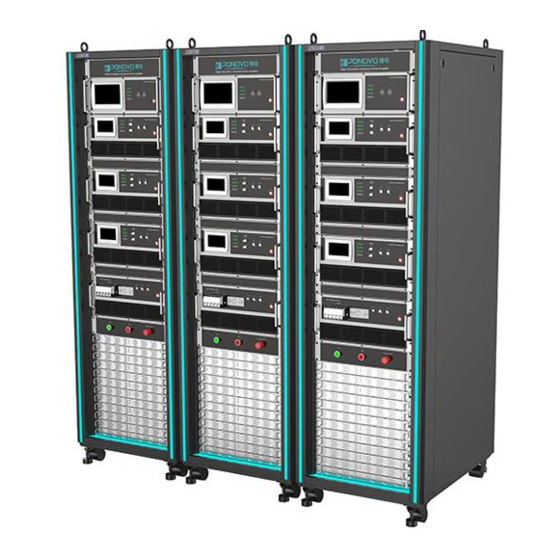
PAV15000 is designed on basis of linearity with quick response, high accuracy and lower distortion. There are two types of test modes to meet different testing purposes. -
Page 8: Main Technical Specifications
PAV15000 Power Amplifier User Manual 3. Main Technical Specifications 3.1 Power Supply Three-phase 380V±10%, 50Hz with capacity 3*30KVA 3.2 Environment Conditions Temperature: 0°C ~ 40°C Related humidity: 20%RH—85%RH Pressure: 86kPa—106kPa Surrounding conditions: No dust, vibration or serious electromagnetic field interferes. -
Page 9: Technical Specifications
PAV15000 Power Amplifier User Manual 3.4 Technical Specifications 4-quandrant Power Amplifier Specifications Description Specification Input signal 0V~±10V Input 20KΩ Impedance Rated: AC 270VAC, DC 382VDC Output voltage Range: AC 0-270VAC, DC 0-±382VDC AC: 15000VA Rated output power DC:15000W 270V /15000V... - Page 10 PAV15000 Power Amplifier User Manual System Monitor Unit Control Output Specifications Description Specification Rated: 270V Power supply Range: 0~270V Output Rated: 50Hz, Frequency Range: 1-5kHz Phase 0-180 Voltage (50Hz) 0.2% (20~270V) Output Phase ≤0.2%(20~270V, 50Hz) accuracy Harmonic distortion Frequency (50Hz)
-
Page 11: Functions And Features
PAV15000 Power Amplifier User Manual 4. Functions and Features The PAV15000 consists of the below parts: 1) High-Performance Control Platform The control platform is cored with ARM processor and FPGA, integrated with the touch-screen to fulfill the monitor and control. -
Page 12: Unit Function And Wiring Connection
PAV15000 Power Amplifier User Manual 5. Unit Function and Wiring Connection 5.1 Main power supply unit The main power supply unit ①Power ON/OFF: It is the master switch to control the amplifier and control unit. ②Pause: the main power supply and amplifier will stop the output after pressing it. It recovers with right rotary. - Page 13 PAV15000 Power Amplifier User Manual Rear panel on main power supply unit ①Control signal input: ②Main power control signal output 1, 2.3: Connect with the monitor unit’s main power socket 1 and 2 via the signal cables. The port 3 is reserved.
-
Page 14: Amplifier
PAV15000 Power Amplifier User Manual 5.2 Power Amplifier Amplifier front panel ①Power: Control the power supply on amplifier ②Run/Stop: Run/ stop the amplifier working ③Monitor signal: Us/ Is, feedback on voltage/ current signal ④Simulation/ System: Show if the signal input is from external simulator or internal system ⑤Normal/ Abnormal indicator: Show the amplifier working status... - Page 15 PAV15000 Power Amplifier User Manual Amplifier rear panel ①AC input: AC220V ②DC voltage: DC power ③Power amplifier output: It connects with the amplifier output on the front panel. ④RJ45 Ethernet: Connect with the PC ⑤Amplifier control input: Connect with the monitor output to send the amplifier status message.
- Page 16 PAV15000 Power Amplifier User Manual I/O terminal panel Ua, Ub, Uc, Un, GND: Three-phase output terminals and block Amplifier output wiring: The cables connecting with Ua, Ub, Uc, U , GND should be stronger than 20mm AWG to connect with the target load.
-
Page 17: Monitor Unit
PAV15000 Power Amplifier User Manual 5.3 System Monitor unit Front panel for monitor unit ①Power: Control the power supply of this unit. ②Run/ Stop: Control the three-phase working status. ③Normal/ Abnormal: Show the monitor status. ④Simulation/ System: Show if the signal input is from external simulator or internal system... - Page 18 PAV15000 Power Amplifier User Manual Rear panel for system monitor unit ①Power input on the monitor unit. ②RJ45 Ethernet port ③Power amplifier output ④Power output ⑤Power amplifier input ⑥DA Out: The Sa, Sb, Sc outputs analog signal 0-±10V to the amplifier units.
-
Page 19: Amplifier Operation
PAV15000 Power Amplifier User Manual 6. Amplifier Operation 6.1 Power On Before power on, please make sure all the wirings are connected well and correct. Follow the steps below to power on. Step 1: Connect with the power source Switch on the main power in the main power unit. -
Page 20: Power Off
PAV15000 Power Amplifier User Manual 6.2 Power off Follow the steps to power off the system. Step 1: Power off the simulation signal Set the signal amplitude as 0 to stop the system working. Step 2: Stop amplifier... -
Page 21: Monitoring And Amplifier Module Operation
PAV15000 Power Amplifier User Manual 7. The Operation of Built-in Software of System Monitoring and Amplifier Module 7.1 System Monitoring Unit Operation 7.1.1 Main Power Supply Main power In the system monitoring built-in module, there are interface of main power, power amplifier, state control, output control and calibration. - Page 22 PAV15000 Power Amplifier User Manual 7.1.2 Power Amplifier Power amplifier In the Power Amplifier page, the power information in each phase can be checked. The power alarm information, power amplifier signal, mode, state and the network connection all can be checked.
- Page 23 PAV15000 Power Amplifier User Manual 7.1.3 State Control State control In the State Control Page, the power will be set here. The default power is 270V. The PA control, voltage/ current and signal can be set as well.
- Page 24 PAV15000 Power Amplifier User Manual 7.1.4 Output Control Output control In the Output Control Page, the amplitude, phase and frequency can be set here providing to the three-phase power module. The default amplitude is 0, phase angle 120º, frequency 50Hz. The output voltage is...
-
Page 25: Power Module Operation
PAV15000 Power Amplifier User Manual 7.2 Power Amplifier Built-In Module Operation 7.2.1 Home Page Home page In the power module, there are Home Page, PA state, PA control, Warnings and Calibration. In the Home page, the PA output, signal, state and mode information can be checked. - Page 26 PAV15000 Power Amplifier User Manual 7.2.2 PA State PA State In the PA State Page, the PA output, power, signal and fault state information can be checked.
- Page 27 PAV15000 Power Amplifier User Manual 7.2.3 PA Control PA Control In the PA Control Page, the voltage source and current model can be changed with the same main power. The PA working status can be controlled here. The default voltage is 270V.
- Page 28 PAV15000 Power Amplifier User Manual 7.2.4 Warnings Warnings If there is fault signal, the fault message will be shown. If the fault message is closed, the latest fault message can be tracked in the warning interface.
Need help?
Do you have a question about the PAV15000 and is the answer not in the manual?
Questions and answers