Brocade Communications Systems VDX6720 Hardware Reference Manual
Hide thumbs
Also See for VDX6720:
- Quick start manual (13 pages) ,
- Hardware reference manual (64 pages)
Table of Contents
Advertisement
Advertisement
Table of Contents

Related Manuals for Brocade Communications Systems VDX6720


Summary of Contents for Brocade Communications Systems VDX6720
- Page 1 53-1002084-01 ® 7 December, 2010 Brocade VDX6720/6730 Hardware Reference Manual...
- Page 2 Wingspan are registered trademarks, and Brocade Assurance, Brocade NET Health, Brocade One, Extraordinary Networks, MyBrocade, and VCS are trademarks of Brocade Communications Systems, Inc., in the United States and/or in other countries. All other brands, products, or service names are or may be trademarks or service marks of, and are used to identify, products or services of their respective owners.
-
Page 3: Table Of Contents
Contents About This Document In this chapter ......... . . vii How this document is organized . - Page 4 Rack installation for a Brocade VDX 6720/6730 ....10 Providing power to the switch....... 10 Verifying operation .
- Page 5 Brocade VDX 6720/6730 maintenance ..... 25 Installing an SFP or SFP+ transceiver ....25 Diagnostic tests .
- Page 6 Regulatory certifications........45 Environmental regulation compliance ......46 China RoHS .
-
Page 7: About This Document
About This Document In this chapter • How this document is organized ........vii •... -
Page 8: Document Conventions
Document conventions This section describes text formatting conventions and important notice formats used in this document. Text formatting The narrative-text formatting conventions that are used are as follows: bold text Identifies command names Identifies the names of user-manipulated GUI elements Identifies keywords and operands Identifies text to enter at the GUI or CLI italic text... -
Page 9: Key Terms
NOTE A note provides a tip, guidance or advice, emphasizes important information, or provides a reference to related information. ATTENTION An Attention statement indicates potential damage to hardware or data. CAUTION A Caution statement alerts you to situations that can be potentially hazardous to you. DANGER A Danger statement indicates conditions or situations that can be potentially lethal or extremely hazardous to you. -
Page 10: Brocade Resources
Brocade resources To get up-to-the-minute information, go to http://my.brocade.com to register at no cost for a user ID and password. For practical discussions about SAN design, implementation, and maintenance, you can obtain Building SANs with Brocade Fabric Switches through: http://www.amazon.com White papers, online demos, and data sheets are available through the Brocade Web site at: http://www.brocade.com/products-solutions/products/index.page For additional Brocade documentation, visit the Brocade Web site:... -
Page 11: Document Feedback
The switch serial number and corresponding bar code are provided on the serial number label, as illustrated below.: *FT00X0054E9* FT00X0054E9 The serial number label is located as follows: • Brocade VDX 6720/6730 — On the switch ID pull-out tab located on the bottom of the port side of the switch Document feedback Quality is our first concern at Brocade and we have made every effort to ensure the accuracy and... - Page 12 Brocade VDX 6720/6730 Hardware Reference Manual 53-1002084-01...
-
Page 13: Chapter 1 Brocade Vdx 6720/6730 Introduction
Chapter Brocade VDX 6720/6730 Introduction In this chapter • Brocade VDX 6720/6730 overview ........1 •... -
Page 14: Vdx 6720/6730-24 Features
Brocade VDX 6720 overview • Extensive diagnostics and system-monitoring capabilities for enhanced high Reliability, Availability, and Serviceability (RAS) • Optimized airflow - a choice of front-to-back or back-to-front flow • A real-time clock (RTC) with battery • SEEPROM for switch identification •... -
Page 15: Views Of The Brocade Vdx 6720/6730-24 Switch
Views of the Brocade VDX 6720-24 switch • Switch Port Analyzer (SPAN), also known as port mirroring Virtualization • Automatic Migration of Port Profiles (AMPP) • Support for VLAN, QoS, security, and FCoE port profiles Convergence/FCoE • Pause Frames(Tx and Rx) •... -
Page 16: Views Of The Brocade Vdx 6720/6730-60 Switch
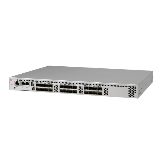
Views of the Brocade VDX 6720-60 switch Figure 1 shows the port side of the Brocade VDX 6720 -24. Switch ID pull-out tab Ethernet management port (RJ45) System power LED RLO management port (RJ45) USB port System status LED Serial console port (RJ45) GbE ports 1 through 24 with status LEDs above FIGURE 1... - Page 17 Views of the Brocade VDX 6720-60 switch Figure 3 shows the port side of the Brocade VDX 6720 -60. Switch ID pull-out tab Ethernet management port (RJ45) Serial console port (RJ45) RLO management port (RJ45) System power LED USB port System status LED GbE ports 1 through 60 with status LEDs above and below...
- Page 18 Views of the Brocade VDX 6720-60 switch Brocade VDX 6720/6730 Hardware Reference Manual 53-1002084-01...
-
Page 19: In This Chapter
Chapter Brocade VDX 6720/6730 Installation In this chapter • Items included with the Brocade VDX 6720/6730 switches ... . 7 • Installation and safety considerations ....... 7 •... -
Page 20: Environmental Considerations
Installation and safety considerations • The primary outlet is correctly wired, protected by a circuit breaker, and grounded in accordance with local electrical codes. • The supply circuit, line fusing, and wire size are adequate, as specified by the electrical rating on the switch nameplate. -
Page 21: Items Required For Installation
Standalone installation for a Brocade VDX 6720/6730 NOTE You should not use tie wraps with optical cables because they are easily overtightened and can damage the optic fibers. Velcro-like wraps are recommended. • Plan for the rack space required for cable management before installing the switch. •... -
Page 22: Rack Installation For A Brocade Vdx 6720/6730
Rack installation for a Brocade VDX 6720 ATTENTION Do not connect the switch to the network until the IP address is correctly set. For instructions on how to set the IP address, see “Setting the switch IP address” on page 13. Rack installation for a Brocade VDX 6720/6730 Follow the installation instructions shipped with the appropriate rack mount kit: •... -
Page 23: Brocade Vdx 6720/6730 Configuration
Chapter Brocade VDX 6720/6730 Configuration In this chapter • Configuration modes for the Brocade VDX 6720/6730 ....11 • Creating a serial connection ........12 •... -
Page 24: Creating A Serial Connection
Creating a serial connection Creating a serial connection You perform all configuration tasks in this guide using a serial connection from a workstation or terminal to the switch. Complete the following steps to create a serial connection to the switch. 1. -
Page 25: Setting The Switch Ip Address
Setting the switch IP address Switch# configure terminal Entering configuration mode terminal switch(config)# username admin password (<WORD>;;User password satisfying password-attributes):******** Setting the switch IP address You can configure the Brocade VDX 6720/6730 with a static IP address, or you can use a Dynamic Host Configuration Protocol (DHCP) server to set the IP address of the switch. -
Page 26: Setting Stateless Ipv6 Autoconfiguration
Enabling and disabling Brocade VCS mode ipv6 address fd00;60;69bc;832;e61f;13ff;fe67;4b94/64 no ipv6 address autoconfig Setting stateless IPv6 autoconfiguration The IPv6 protocol allows assignment of multiple IP addresses to each network interface. Each interface is configured with a link local address in almost all cases, but this address is only accessible from other hosts on the same network. -
Page 27: Disabling Vcs Mode
Setting the date and time You are prompted to enter a unique RBridge ID. 3. Reboot the switch. When the switch comes back up, if it is connected to other VCS-enabled switches the negotiation protocols begin, determining which switch in the fabric is the principle switch and making sure that all domain IDs, and therefore RBRidge IDs, are unique. -
Page 28: Understanding Time Zones
Setting the date and time Understanding time zones You can set the time zone for a switch using the clock TimeZone command. The time zone setting has the following characteristics: • The clock TimeZone setting automatically adjusts for Daylight Savings Time. •... -
Page 29: Setting The Clock (Date And Time)
Connecting network devices switch:admin> show ntp status [switchid <switchid> | all] 132.163.135.131 The request is for the local switch unless a switchid is specified. Specify the all parameter to send the request to all switches in the cluster. If you need to remove an NTP server, use the following example: switch:admin>... -
Page 30: Connecting Network Devices
Creating Brocade inter-switch link trunks NOTE The 802.3ab standard (automatic MDI or MDIX detection) calls for automatic negotiation of the connection between two 1000Base-T ports. Therefore, a crossover cable may not be required; a straight-through cable may work as well. Connecting to workstations, servers, or routers Straight-through UTP cabling is required for direct UTP attachment to workstations, servers, or routers using network interface cards (NICs). -
Page 31: Brocade Vdx 6720/6730 Operation
Chapter Brocade VDX 6720/6730 Operation In this chapter • Powering on the Brocade VDX 6720/6730 ......19 •... -
Page 32: Led Locations
LED activity interpretation • One bicolor (green and amber) port status LED for each port on the switch. These LEDs are arrayed above each pair of Ethernet ports on the VDX 6720/6730-24 and below each pair on the VDX 6720/6730-60. The left LED corresponds to the upper port of the pair and the right LED corresponds to the lower port. - Page 33 LED activity interpretation System power LED RLO management Ethernet port link LED System status LED RLO management Ethernet port activity LED Switch management Ethernet port link LED GbE port status LED (port 1 - top row) Switch management Ethernet port activity GbE port status LED (port 6 - bottom row) FIGURE 7 LEDs on port side of Brocade VDX 6720/6730-60...
-
Page 34: Led Patterns
LED activity interpretation LED patterns Table 2 describes the port side LEDs and their behaviors. TABLE 2 Port side LED patterns during normal operation LED name LED color Status of hardware Recommended action System power Off (no light) System is off or there is an Verify the system is powered on (power internal power supply failure. - Page 35 LED activity interpretation Table 3 describes the LEDs on the non-port side of the switches. TABLE 3 Non-port side LED patterns during normal operation LED name LED color Status of hardware Recommended action Power supply Off (no light) Assembly is not receiving power Verify the assembly is on and seated and fan or is turned off.
-
Page 36: Post And Boot Specifications
POST and boot specifications TABLE 3 Non-port side LED patterns during normal operation (Continued) LED name LED color Status of hardware Recommended action Fan status Off (no light) Fan assembly is not receiving Try the following: (VDX 6720-60 power. Verify the fan assembly is seated correctly. -
Page 37: Interpreting Post Results
Interpreting POST results • Obtains a domain ID and assigns port addresses. • Constructs unicast routing tables. • Enables normal port operation. Interpreting POST results POST is a system check that is performed each time the switch is powered on, rebooted, or reset. During POST, the LEDs flash either amber or green. -
Page 38: Diagnostic Tests
Brocade VDX 6720 maintenance 1. Making sure that the bail (wire handle) is in the unlocked position, place the SFP or SFP+ transceiver in the correctly oriented position on the port, as shown in Figure 2. Slide the SFP or SFP+ transceiver into the port until you feel it click into place; then close the bail. -
Page 39: Brocade Vdx 6720/6730 Management
Brocade VDX 6720 management Diagnostic tests run at link speeds of 1 or 10 Gbps (DCB) depending on the speed of the link being tested and the type of port. NOTE Diagnostic tests might temporarily lock the transmit and receive speed of the links during diagnostic testing. - Page 40 Brocade VDX 6720 management Brocade VDX 6720/6730 Hardware Reference Manual 53-1002084-01...
-
Page 41: Fru Removal And Replacement Procedures
Chapter FRU Removal and Replacement Procedures In this chapter • Before beginning the installation ......... 29 •... -
Page 42: Replacing A Combined Power Supply And Fan Assembly In A Vdx 6720/6730-24
Replacing a combined power supply and fan assembly in a VDX 6720-24 Examples of airflow symbols: AIRFLOW AIRFLOW FIGURE 10 Examples of airflow symbols: The green E symbol indicates an exhaust FRU. This unit pulls air in from the port side of the switch and exhausts it out the non-port side. -
Page 43: Time Required
Replacing a combined power supply and fan assembly in a VDX 6720-24 empty longer than two minutes while the switch is operating. If a fan assembly fails, leave it in the switch until it can be replaced. Maintain all fan assemblies in operational condition to provide redundancy. -
Page 44: Replacing The Power Supply And Fan Assembly
Replacing a combined power supply and fan assembly in a VDX 6720/6730-24 Replacing the power supply and fan assembly Complete the following steps to replace a combined power supply and fan assembly in a Brocade VDX 6720/6730-24. 1. Unscrew the captive screw on the power supply and fan assembly you are replacing using the Phillips screwdriver. -
Page 45: Replacing A Power Supply Fru In A Vdx 6720/6730-60
Replacing a power supply FRU in a VDX 6720-60 Brocade VDX 6720/6730-24 chassis Label with part number Power supply and fan assembly Captive screw FIGURE 12 Orientation of the power supply and fan assembly in the Brocade VDX 6720/6730-24 4. Verify that the power supply and fan assembly status LED is steady green to indicate normal operation (see Table 5 for more LED information). -
Page 46: Determining The Need To Replace A Power Supply
Replacing a power supply FRU in a VDX 6720-60 TABLE 6 Brocade VDX 6720/6730-60 power supply status LED behavior, description, and required actions LED color and behavior Description Action required Off (no light) Power supply is not receiving power or is off. Verify that the power supply is on and seated and the power cord is connected to a functioning power... - Page 47 Replacing a power supply FRU in a VDX 6720-60 3. Using the Phillips screwdriver, unscrew the two captive screws on the power supply. 4. Remove the power supply from the chassis by pulling the handle on the power supply out and away from the chassis.
-
Page 48: Replacing A Fan Assembly In The Vdx 6720/6730-60
Replacing a fan assembly in the VDX 6720/6730 You can also enter one of the following commands at the command line prompt to display power supply status. • show chassis • show environment power Replacing a fan assembly in the VDX 6720/6730-60 The Brocade VDX 6720/6730-60 has three fan assemblies as displayed in Figure 15. -
Page 49: Determining The Need To Replace A Fan Assembly
Replacing a fan assembly in the VDX 6720-60 Table 7 describes the fan assembly status LED colors, behaviors, and actions required, if any TABLE 7 Brocade VDX 6720/6730-60 fan assembly status LED behavior, description, and required actions LED color and behavior Description Action required Off (no light) - Page 50 Replacing a fan assembly in the VDX 6720/6730-60 1. Using the Phillips screwdriver, unscrew the captive screw on the fan assembly. 2. Remove the fan assembly from the chassis by pulling the handle on the fan assembly out and away from the chassis. 3.
-
Page 51: Brocade Vdx 6720/6730 Specifications
Appendix Brocade VDX 6720/6730 Specifications In this appendix • Weight and physical dimensions ........39 •... -
Page 52: Power Supply Specifications
Power supply specifications TABLE 9 Facility requirements T ype Requirements • Electrical Primary AC input 85-265 VAC nominal, 47-63 Hz; switch autosenses input voltage • Adequate supply circuit, line fusing, and wire size, as specified by the electrical rating on the switch nameplate •... -
Page 53: Environmental Requirements
Environmental requirements Environmental requirements Table 11 lists the acceptable environmental ranges for both operating and nonoperating (such as during transportation or storage) conditions. TABLE 11 Environmental requirements Condition Acceptable during operation Acceptable during non-operation Ambient 0º to 40º C -25º to 70º C Temperature 32º... -
Page 54: Data Transmission Ranges
Data transmission ranges Data transmission ranges Table 13 provides the data transmission ranges for different cable types and port speeds for all ports. TABLE 13 Data transmission ranges Cable and connector type Connector Cable Distance Passive copper SFP+ copper Twin axial <10m (32.81 ft) SFP+ copper Twin axial... -
Page 55: Fcc Warning (Us Only)
Regulatory compliance • “Electrical safety” FCC warning (US only) This equipment has been tested and complies with the limits for a Class A computing device pursuant to Part 15 of the FCC Rules. These limits are designed to provide reasonable protection against harmful interference when the equipment is operated in a commercial environment. -
Page 56: Power Cords (Japan Denan)
Regulatory compliance Power cords (Japan Denan) BSMI statement (Taiwan) CE statement ATTENTION This is a Class A product. In a domestic environment, this product might cause radio interference, and the user might be required to take corrective measures The standards compliance label on the Brocade VDX 6720/6730 contains the CE mark which indicates that this system conforms to the provisions of the following European Council directives, laws, and standards: •... -
Page 57: Rtc Battery
Regulatory certifications ATTENTION Use only optical transceivers that are qualified by Brocade Communications Systems, Inc. and comply with the FDA Class 1 radiation performance requirements defined in 21 CFR Subchapter I, and with IEC 825-2. Optical products that do not comply with these standards might emit light that is hazardous to the eyes. -
Page 58: Environmental Regulation Compliance
Environmental regulation compliance TABLE 15 Regulatory compliance standards Country Standards Agency certifications and markings Safety Safety United States Bi-Nat UL/CSA 60950-1 ANSI C63.4 cCSAus FCC Class A and 1st Ed or latest Statement Canada Bi-Nat UL/CSA 60950-1 ICES-003 Class A cCSAus ICES A and Statement 1st Ed or latest... - Page 59 Environmental regulation compliance The EPUP assumes that the product will be used under normal conditions in accordance with the operating manual of the product. (EPUP) EPUP Brocade Brocade ocade EPUP Brocade VDX 6720/6730 Hardware Reference Manual 53-1002084-01...
-
Page 60: Ts/Hs Dual Language Sheet
Environmental regulation compliance TS/HS dual language sheet In accordance with China's Management Measures on the Control of Pollution caused by Electronic Information products (Decree No. 39 by the Ministry of Information Industry), the information in Table 16 is provided regarding the names and concentration level of Hazardous substances (HS) which may be contained in this product. - Page 61 Environmental regulation compliance Brocade VDX 6720/6730 Hardware Reference Manual 53-1002084-01...
- Page 62 Environmental regulation compliance Brocade VDX 6720/6730 Hardware Reference Manual 53-1002084-01...
- Page 63 Index command clock set clock timezone access NTP server configure terminal airflow symbols copy running-config startup-config airflow warning fastboot ip address ip address dhcp ip gateway-address ipv6 address autoconfig boot no diag post boot flash memory no ipv6 address autoconfig BSMI statement (Taiwan) no ntp server no vcs enable...
- Page 64 distributed intelligence inter-switch links ip address command ip address dhcp ip gateway-address ipv6 address autoconfig command electrical ISL trunking considerations items included with the Brocade VDX 6720 safety EMC compliance environmental considerations requirements KCC statement (Republic of Korea) event date and time laser compliance facility requirements LEDs...
- Page 65 software features specifications general overview memory power supplies static IP address IPv4 IPv6 physical dimensions switch platform components capabilities ports on demand (POD) management POST switch IP address POST and boot specifications static power cord statement (Japan Denan) using DHCP power supplies synchronize local time using NTP replacing...
- Page 66 weight Brocade VDX 6720/6730 Hardware Reference Manual 53-1002084-01...
Need help?
Do you have a question about the VDX6720 and is the answer not in the manual?
Questions and answers