Brocade Communications Systems VDX6720 Hardware Reference Manual
Data center switch
Hide thumbs
Also See for VDX6720:
- Quick start manual (13 pages) ,
- Hardware reference manual (66 pages)
Table of Contents
Advertisement
Advertisement
Table of Contents

Related Manuals for Brocade Communications Systems VDX6720


Summary of Contents for Brocade Communications Systems VDX6720
- Page 1 ® 53-100xxxx-01 December xx, 2010 Brocade VDX6720 Hardware Reference Manual...
- Page 2 Wingspan are registered trademarks, and Brocade Assurance, Brocade NET Health, Brocade One, Extraordinary Networks, MyBrocade, and VCS are trademarks of Brocade Communications Systems, Inc., in the United States and/or in other countries. All other brands, products, or service names are or may be trademarks or service marks of, and are used to identify, products or services of their respective owners.
-
Page 3: Table Of Contents
Platform components and capabilities..... 1 VDX6720-24 features ........2 VDX6720-60 features . - Page 4 LED activity interpretation ....... . . 17 Brocade VDX6720 LEDs ....... 17 LED locations .
- Page 5 China RoHS ......... 45 Index Brocade VDX6720 Hardware Reference Manual 53-100xxxx-01...
- Page 6 Brocade VDX6720 Hardware Reference Manual 53-100xxxx-01...
-
Page 7: About This Document
• The Index points you to the exact pages on which specific information is located. Supported hardware and software This document is specific to the Brocade VDX6720 and Network OS v2.0.0. Brocade VDX6720 Hardware Reference Manual 53-100xxxx-01... -
Page 8: What's New In This Document
< >. Repeat the previous element, for example “member[;member...]” value Fixed values following arguments are printed in plain font. For example, show WWN Boolean. Elements are exclusive. Example: show mode egress | ingress viii Brocade VDX6720 Hardware Reference Manual 53-100xxxx-01... -
Page 9: Notes, Cautions, And Warnings
Referenced Trademarks and Products Microsoft Corporation Windows, Windows NT, Internet Explorer Sun Microsystems, Inc. Sun, Solaris Netscape Communications Corporation Netscape Red Hat, Inc. Red Hat, Red Hat Network, Maximum RPM, Linux Undercover Velcro Industries B.V. Velcro Brocade VDX6720 Hardware Reference Manual 53-100xxxx-01... -
Page 10: Additional Information
To expedite your call, have the following information available: 1. General Information • Switch model • Switch operating system version • Error numbers and messages received • supportSave command output Brocade VDX6720 Hardware Reference Manual 53-100xxxx-01... -
Page 11: Document Feedback
Brocade 300, 4100, 4900, 5100, 5300, 7500, 8000, and Brocade Encryption Switch—On the switch ID pull-out tab located inside the chassis on the port side on the left • Brocade 5000, Brocade VDX6720—On the switch ID pull-out tab located on the bottom of the port side of the switch •... - Page 12 Brocade VDX6720 Hardware Reference Manual 53-100xxxx-01...
-
Page 13: Chapter 1 Brocade Vdx6720 Introduction
Brocade VDX6720 overview ........ -
Page 14: Vdx6720-24 Features
60 10GbE SFP+ ports (also configurable to 1 GbE) • Nine eAnvil ASICs arranged in a 3/6, core/edge configuration • 600ns-1.8μs port-to-port latency • 17” depth • Dual, redundant, hot-swappable 500W AC power supplies • Triple, redundant, hot-swappable cooling fans Brocade VDX6720 Hardware Reference Manual 53-100xxxx-01... -
Page 15: Software Features
Brocade VDX6720 overview Software features The Brocade VDX6720 family supports the following features. For more details on these, see the Brocade Network OS Administrator’s Guide. L2/L3 security features • VLANs • Spanning Tree (STP, RSTP, MSTP) PVST+/PVRST+ • Support unicast and multicast capabilities, IGMP snooping •... -
Page 16: Port Side Of The Brocade Vdx6720 Family
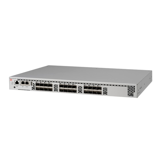
VCS licensing Port side of the Brocade VDX6720 family The port side of the Brocade VDX6720 family includes the system status LED, console port, Ethernet port and LEDs, USB port, GbE ports, and Fibre Channel ports and the corresponding port status LEDs. -
Page 17: Non-Port Side Of The Brocade Vdx6720 Family
System status LED GbE ports 1-60 Non-port side of the Brocade VDX6720 family Figure 3 shows the non-port side of the Brocade VDX6720-24, which contains the combined power supplies and fans. FIGURE 3 Non-port side of the Brocade VDX6720-24 Power supply/fan assemby #2... - Page 18 Non-port side of the Brocade VDX6720 family Figure 4 shows the non-port side of the Brocade VDX6720-60, which contains the integrated power supplies and fans. FIGURE 4 Non-port side of the Brocade VDX6720-60 Power supply status LED Fan assembly #1...
-
Page 19: In This Chapter
In this chapter • Items included with the Brocade VDX6720......7 • Installation and safety considerations ....... 7 •... -
Page 20: Electrical Considerations
The cabinet must be a standard EIA cabinet. • A cabinet space that is one rack unit (1U for VDX6720-24) or two rack units (2U for VDX6720-60) high depending on the platform ordered; 4.45 cm (1.75 inches) or 8.90 cm (3.50 inches) high and 48.3 cm (19 inches) wide. -
Page 21: Items Required For Installation
• Keep LEDs visible by routing port cables and other cables away from the LEDs. Items required for installation The following items are required for installing, configuring, and connecting the Brocade VDX6720 for use in a network and fabric: •... -
Page 22: Cabinet Installation For A Brocade Vdx6720
AC failure. Ensure that the cords have a minimum service loop of 6 in. available and are routed to avoid stress. 2. Power on the power supplies by flipping both AC switches to the “I” symbol (VDX6720-24 only, power supplies for VDX6720-60 power up automatically when plugged in). The power supply LEDs display amber until POST is complete, and then change to green. -
Page 23: Chapter 3 Brocade Vdx6720 Configuration
• Configuring the Brocade VDX6720 ....... . 11 Configuring the Brocade VDX6720 Something about the ease of configuring the switch and the automatic formation of the Ethernet fabric when VCS is enabled. -
Page 24: Switch Ip Address
Configuring the Brocade VDX6720 Switch IP address You can configure the Brocade VDX6720 with a static IP address, or you can use a DHCP (Dynamic Host Configuration Protocol) server to set the IP address of the switch. DHCP is enabled by default. -
Page 25: Setting The Date
NTP server fails. The principal or primary FCS switch synchronizes its time with the NTP server every 64 seconds. Setting the date 1. Log into the switch using the default password, which is password. 2. Enter the d d ate command, using the following syntax: Brocade VDX6720 Hardware Reference Manual 53-100xxxx-01... -
Page 26: Setting Time Zones
Please identify a location so that time zone rules can be set correctly. 3. Enter the appropriate n n umber or C C trl-D to quit. 4. At the prompt, select a c c ountry location. Brocade VDX6720 Hardware Reference Manual 53-100xxxx-01... -
Page 27: Brocade Inter-Switch Link (Isl) Trunking
Brocade Inter-Switch Link (ISL) Trunking Unless specifically disabled, ISL trunking between switches is automatic. No separate licensing is required. For more information about ISL Trunking, see the Brocade Network OS Administrator’s Guide. Brocade VDX6720 Hardware Reference Manual 53-100xxxx-01... - Page 28 Configuring the Brocade VDX6720 Brocade VDX6720 Hardware Reference Manual 53-100xxxx-01...
-
Page 29: In This Chapter
• Brocade VDX6720 Maintenance ........23 •... -
Page 30: Led Locations
LED locations Figure 5 shows the port side of the Brocade VDX6720. The port status LEDs for both the GbE and FC ports are vertically staggered to correspond to the upper and lower ports in each pair. Refer to Figure 1 for the locations of the GbE and FC ports. - Page 31 LED activity interpretation Figure 6 shows the LEDs on the non-port side of the VDX6720-24. Power supply/fan assembly #2 status LED Power supply/fan assembly #1 status LED FIGURE 6 LEDs on non-port side of Brocade VDX6720-24 System power LED RLO management Ethernet link LED...
-
Page 32: Led Patterns
LED activity interpretation Figure 6 shows the LEDs on the non-port side of the VDX6720-60. Power supply #2 status LED Fan assembly #2 status LED Power supply #1 status LED Fan assembly #3 status LED Fan assembly #1 status LED... - Page 33 Check the power switch and plug been turned off or the unit has been unplugged Note: When the switch is first powered on the assembly status LED will show amber until POST has completed. Brocade VDX6720 Hardware Reference Manual 53-100xxxx-01...
-
Page 34: Post And Boot Specifications
The success or failure results of the diagnostic tests that run during POST can be monitored through LED activity, the error log, or the command line interface. POST includes the following tasks: 1. Conducts preliminary POST diagnostics. 2. Initializes the operating system. 3. Initializes hardware. Brocade VDX6720 Hardware Reference Manual 53-100xxxx-01... -
Page 35: Boot
Brocade Network OS Administrator’s Guide. For information about error messages, refer to the Message Reference Manual. Brocade VDX6720 Maintenance The Brocade VDX6720 is designed for high availability and low failure; it does not require any regular physical maintenance. It includes diagnostic tests and field-replaceable units, described in the following sections. -
Page 36: Installing An Sfp Or Sfp+ Transceiver
Short Wavelength (SWL) and Long Wavelength (LWL) optical media. For its DCB connections, the Brocade VDX6720 uses SFP+ transceivers that support either optical or Brocade-branded active twinax copper cables. The optical SFP+ transceivers support both SR (Short Reach) and LR (Long Reach) modules. -
Page 37: Brocade Vdx6720 Management
Diagnostic tests might temporarily lock the transmit and receive speed of the links during diagnostic testing. Brocade VDX6720 Management You can use the management functions built into the Brocade VDX6720 to monitor the fabric topology, port status, physical status, and other information to help you analyze switch performance and to accelerate system debugging. - Page 38 Brocade VDX6720 Management Brocade VDX6720 Hardware Reference Manual 53-100xxxx-01...
-
Page 39: Chapter 5 Fru Removal And Replacement Procedures
Installing a power supply FRU in the VDX6720-60 ....31 • Installing a fan FRU in the VDX6720-60 ......34 Introduction... -
Page 40: Replacing A Combined Power Supply And Fan Fru In A Vdx6720-2428
Replacing a combined power supply and fan FRU in a VDX6720-24 Figure 11 shows the two combined power supply and fan assemblies in the Brocade VDX6720-24. The Network OS identifies the FRUs from left to right as assembly #2 and assembly #1. - Page 41 Replacing a combined power supply/fan assembly in the switch should take less than two minutes. Items required You need the following items to replace a fan assembly in a Brocade VDX6720-24: • New power supply and fan assembly FRU (must have the same part number as the FRU being replaced) •...
- Page 42 Orient the new fan assembly as shown in Figure 12, with the captive screw on the right. FIGURE 12 Orientation of the power supply and fan assembly FRU in the Brocade VDX6720-24 P/N: xxxxxxx-xx Brocade VDX6720-24 chassis Label with part number...
-
Page 43: Installing A Power Supply Fru In The Vdx6720-60
Brocade VDX6720-60 is operating. If a power supply fails, leave the power supply in the Brocade VDX6720-60 until it can be replaced. Maintain both power supplies in operational condition to provide redundancy. -
Page 44: Determining The Need To Replace A Power Supply
,60-0300031-01,X3, ,SP640-2P ,TQ2H0000 br5300:admin> Time Required Replacing a power supply in the Brocade VDX6720-60 should require less than two minutes to complete. Items Required The following items are required to replace a power supply: • New power supply (must have the same part number as the FRU being replaced) •... - Page 45 Installing a power supply FRU in the VDX6720-60 1. To leave the Brocade VDX6720-60 in service while replacing a power supply, verify that the other power supply (the one not being replaced) has been powered on for at least four seconds and has a steady green LED.
-
Page 46: Installing A Fan Fru In The Vdx6720-60
9. All fan assemblies and power supplies must have the same airflow symbol (E E or I) to be compatible with each other. Installing a fan FRU in the VDX6720-60 The Brocade VDX6720-60 has three fan assemblies as displayed in Figure 15. The Network OS identifies the fan locations from left to right as fan #3, fan #2, and fan #1. -
Page 47: Determining The Need To Replace A Fan Assembly
Fan 3 is Ok, speed is 4891 RPM br5300:admin> Time required Replacing a fan assembly in the Brocade VDX6720-60 should require less than two minutes to complete. Items required The following items are required to replace a fan assembly in the Brocade VDX6720-60: •... - Page 48 Using the Phillips-head screwdriver, secure the fan assembly to the chassis by tightening in the captive screw. FIGURE 16 Inserting the fan assembly in the Brocade VDX6720-60 4. Verify that the fan status LED is lit (steady green) to indicate normal operation (see Table 5.
-
Page 49: In This Appendix
Environmental regulation compliance ......44 Switch components The Brocade VDX6720 platforms include the following components: VDX6720-24 •... -
Page 50: Weight And Physical Dimensions
Weight (with all power supplies and fan assemblies, and ??? kg (??? lb) - VDX6720-24 no SFPs installed) ??? kg (??? lb) - VDX6720-60 Facility requirements Table 8 provides the facilities requirements that must be met for the Brocade VDX6720. TABLE 8 Facility Requirements Type Requirements •... -
Page 51: Power Supply Specifications
Each power supply has a built-in fan for cooling, pushing air towards the port side of the switch. Table 9 lists the power supply specifications for the Brocade VDX6720. TABLE 9 Power Supply Specifications... -
Page 52: General Specifications
General specifications General specifications Table 11 lists the general specifications for the Brocade VDX6720. TABLE 11 General specifications Specification Description Configurable port types F_Port, FL_Port, E_Port, and M_Port System architecture Nonblocking shared-memory switch System processor Freescale MPC8548 x 1.3GHz Aggregate switch I/O bandwidth... -
Page 53: Memory Specifications
Memory specifications Memory specifications The Brocade VDX6720 has three types of memory devices, boot flash, compact flash, and main memory. The size of each is listed in the following table. TABLE 13 Brocade VDX6720 memory specifications Type Size Boot flash... -
Page 54: Kcc Statement (Republic Of Korea)
When such trouble occurs, the user might be required to take corrective actions. Power cords (Japan Denan) BSMI statement (Taiwan) The BSMI Statement is applicable to Brocade VDX6720 power supplies. CE statement ATTENTION This is a Class A product. In a domestic environment, this product might cause radio interference,... -
Page 55: Canadian Requirements
Regulatory compliance The standards compliance label on the Brocade VDX6720 contains the CE mark which indicates that this system conforms to the provisions of the following European Council directives, laws, and standards: • Electromagnetic Compatibility (EMC) Directive 2004/108/EEC • Low Voltage Directive (LVD) 2006/95/EC •... -
Page 56: Regulatory Certifications
IT power system. Regulatory certifications Table 14 lists the regulatory compliance standards for which the Brocade VDX6720 is certified. TABLE 14 Regulatory compliance standards Country... -
Page 57: China Rohs
China ROHS hazardous substances/toxic substances (HS/TS) concentration chart Name of the Hazardous/Toxic Substance/Elements Component Lead (PB) Mercury Cadium Hexavalent Polybrominated Polybrominated (Hg) (CD) Chromium Biphenyl (PBB) Diphenyl Ether (CR6+) (PBDE) Fibre Channel Switch Fan, Blower assemblies PCBA cards Power Supply kit Brocade VDX6720 Hardware Reference Manual 53-100xxxx-01... - Page 58 Replacement Doors Software/ Documentation X indicates that the concentration of such hazardous/toxic substance in all the units of homogeneous material of such component is higher than the SJ/T11363-2006 Requirements for Concentration Limits. Brocade VDX6720 Hardware Reference Manual 53-100xxxx-01...
- Page 59 Environmental regulation compliance O indicates that no such substances are used or that the concentration is within the aforementioned limits. Brocade VDX6720 Hardware Reference Manual 53-100xxxx-01...
- Page 60 Environmental regulation compliance Brocade VDX6720 Hardware Reference Manual 53-100xxxx-01...
-
Page 61: Index
Command line interface (CLI) fan assembly compact flash memory replacing fans fanShow command fastboot command FCC warning (US only) Fibre Channel Association Brocade VDX6720 Hardware Reference Manual 53-100xxxx-01... - Page 62 LEDs FRUs airflow warning main memory fan assembly, replacing in VDX6720-60 maintenance power supply, replacing in VDX6720-60 Management Server removing and replacing memory specifications replacing combined FRU in VDX670-24 monitoring through LED activity general specifications non-port side view...
- Page 63 DHCP switchShow synchronize local time using NTP terminal emulator configuration time and date time zones trunking group tsclockserver tsTimeZone VCCI statement VDX6720-24 non-port side LED indications VDX6720-60 fan LED indications power supply LED indications Brocade VDX6720 Hardware Reference Manual 53-100xxxx-01...
- Page 64 Brocade VDX6720 Hardware Reference Manual 53-100xxxx-01...
Need help?
Do you have a question about the VDX6720 and is the answer not in the manual?
Questions and answers