Advertisement
RG-C811A, RG-C811HA
Model No.
GENERAL SAFETY INFORMATION
To reduce the risk of injury, loss of life, electric shock, fire, malfunction, and damage to equipment or property, always
observe the following safety precautions.
The following symbol word panels are used to classify and describe the level of hazard, injury, and property damage
caused when the denotation is disregarded and improper use is performed.
WARNING
CAUTION
The following symbols are used to classify and describe the type of instructions to be observed.
This symbol is used to alert users to a specific operating procedure that must be followed in order to
operate this unit safely.
This symbol is used to alert users to a specific operating procedure that must not be performed.
This symbol is used to alert users not to disassemble the equipment.
This symbol is used to alert users to make sure of grounding when using the equipment with the grounding
terminal.
Denotes a potential hazard that could result in serious injury or death.
Denotes a hazard that could result in minor injury.
Denotes a hazard that could result in property damage.
INSTALLATION INSTRUCTIONS
READ AND SAVE THESE INSTRUCTIONS
Thank you for purchasing this Panasonic product.
Please read these instructions carefully before attempting
to install, operate or service the Panasonic product. Please
carefully read the "GENERAL SAFETY INFORMATION".
Failure to comply with instructions could result in personal
injury or property damage. Please explain to users how to
operate and maintain the product after installation and this
manual should be presented to users. Please retain this
manual for future references.
See page 12 for "Panasonic Warranty Sheet".
Ventilating Fan
C8 1 1 A1 4 2 0 A
Advertisement
Table of Contents

Related Manuals for Panasonic RG-C811A


Summary of Contents for Panasonic RG-C811A
- Page 1 READ AND SAVE THESE INSTRUCTIONS Thank you for purchasing this Panasonic product. Please read these instructions carefully before attempting to install, operate or service the Panasonic product. Please carefully read the “GENERAL SAFETY INFORMATION”. Failure to comply with instructions could result in personal injury or property damage.
- Page 2 GENERAL SAFETY INFORMATION (CONTINUED) WARNING To reduce the risk of fire, electric shock or injury to persons, observe the following: Use this unit only in the manner intended by the manufacturer. If you have any questions, contact the manufacturer. Before servicing or cleaning unit, switch power off at service panel and lock the service disconnecting means to prevent power from being switched on accidentally.
- Page 3 (RG-C811HA only) This Panasonic ventilating fan model is equipped with a humidity sensor that turns on automatically when humidity increases rapidly, or when humidity rises above a 30% - 80% relative humidity set-point. It is user-adjustable to...
-
Page 4: Supplied Accesories
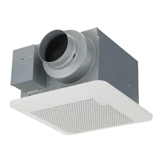
Flex-Z Fast ™ bracket (with 4 Self-drilling tapping screws screw - ST4.2X20) DIMENSIONS Unit: inches (mm) 1 1/2 (37) RG-C811A 4 1/2 (114) 7/8 (23.5) 7 1/2 (190) 13 (330) Part name Part name Blade Pick-A-Flow™ switch Grille Fan body... -
Page 5: Wiring Diagram
Damper Adaptor Flex-Z Fast™ bracket PCB box Selector 3 7/8 Humidity sensor 10 1/4 (261) (100) WIRING DIAGRAM RG-C811A Fan body Junction box Neutral White Main control circuit AC 120 V 60 Hz (Power supply) Black Live (Fan) Main control... -
Page 6: Installation (Retrofit)
The Pick-A-Flow™ switch on the face of the product allows the option to choose 80 or 110 CFM. This product can run continuously or intermittently, depending upon the needs of the owner. Air volume (CFM) Factory setting 0811 MODEL RG-C811A 80 CFM Pick-A-Flow™ RG-C811HA 80 CFM switch 1315 MODEL... - Page 7 INSTALLATION (RETROFIT) (CONTINUED) Remove adaptor Adaptor Machine screw from fan body (M4X8) Disconnect plug connector from the receptacle and remove adaptor Plug connector from fan body by removing the machine screw (M4X8) before installation. Fan body Receptacle Unit: inches (mm) Remove existing fan Conduit Circular duct...
- Page 8 INSTALLATION (RETROFIT) (CONTINUED) Insert circular exhaust duct Conduit Circular exhaust duct Conduit WHITE Mastic or BLACK GREEN approved Junction Earth ground Wire nuts foil tape Knock-out hole Switch box Junction box Neutral cover AC 120 V 2 Self-drilling screws 2 Self-drilling screws 60 Hz Earth ground LINE IN...
-
Page 9: Installation (New Construction)
INSTALLATION (RETROFIT) (CONTINUED) Sealing Once fan body is mounted and secure, fill gap between flange and ceiling with caulk or other sealant to prevent air leakage. Joist Joist Adjust Pick-A-Flow™ switch. (Refer to explanation under FEATURES). (Page 6) Install grille Drywall Mounting spring Insert the mounting springs into the slot as... -
Page 10: Maintenance & Cleaning
INSTALLATION (NEW CONSTRUCTION) (CONTINUED) Joist Extend bracket to the other joist. Install bracket to joist by using 2-preinstalled tapping screws. 2 Tapping screws (ST4.2X20) Follow steps from “RETROFIT” Installation Follow the steps 4 to 7 on “INSTALLATION (RETROFIT)”. MAINTENANCE (CLEANING) Disconnect power source before working on unit. -
Page 11: Maintenance Of Unit
Warning Concerning Removal of Covers. The unit should be serviced by qualified technicians only. Your product is designed and manufactured to ensure a minimum of maintenance. Should your unit require service or parts, call Panasonic Call Center at 1-866-292-7299 (USA). - Page 12 USA, in the event of defects in material or workmanship in accordance to the following: Service in the USA, can be obtained during the warranty period by contacting the selling Distributor or Panasonic Customer Call Center at 1-866-292-7299, toll free.
Need help?
Do you have a question about the RG-C811A and is the answer not in the manual?
Questions and answers