Table of Contents
Advertisement
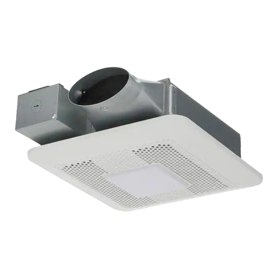
Model No.
RG-T810LA
GENERAL SAFETY INFORMATION
To reduce the risk of injury, loss of life, electric shock, fire, malfunction, and damage to equipment or property, always
observe the following safety precautions.
The following symbol word panels are used to classify and describe the level of hazard, injury, and property damage
caused when the denotation is disregarded and improper use is performed.
WARNING
CAUTION
The following symbols are used to classify and describe the type of instructions to be observed.
This symbol is used to alert users to a specific operating procedure that must be followed in order to
operate this unit safely.
This symbol is used to alert users to a specific operating procedure that must not be performed.
This symbol is used to alert users not to disassemble the equipment.
This symbol is used to alert users to make sure of grounding when using the equipment with the grounding
terminal.
READ AND SAVE THESE INSTRUCTIONS
Thank you for purchasing this Panasonic product.
Please read these instructions carefully before attempting to
install, operate or service the Panasonic product. Please
carefully read the "GENERAL SAFETY INFORMATION".
Failure to comply with instructions could result in personal
injury or property damage. Please explain to users how to
operate and maintain the product after installation and this
manual should be presented to users. Please retain this
manual for future references.
Denotes a potential hazard that could result in serious injury or death.
Denotes a hazard that could result in minor injury.
Denotes a hazard that could result in property damage.
INSTALLATION INSTRUCTIONS
See page 12 for "Panasonic Warranty Sheet".
Ventilating Fan
T8 1 0 L1 4 2 0 A
Advertisement
Table of Contents

Related Manuals for Panasonic RG-T810LA


Summary of Contents for Panasonic RG-T810LA
- Page 1 READ AND SAVE THESE INSTRUCTIONS Thank you for purchasing this Panasonic product. Please read these instructions carefully before attempting to install, operate or service the Panasonic product. Please carefully read the “GENERAL SAFETY INFORMATION”. Failure to comply with instructions could result in personal injury or property damage.
- Page 2 GENERAL SAFETY INFORMATION (CONTINUED) WARNING To reduce the risk of fire, electric shock or injury to persons, observe the following: Use this unit only in the manner intended by the manufacturer. If you have any questions, contact the manufacturer. Before servicing or cleaning unit, switch power off at service panel and lock the service disconnecting means to prevent power from being switched on accidentally.
- Page 3 Also, any changes or modifications not expressly approved by the party responsible for compliance could void the user’s authority to operate this equipment. SDoC Responsible Party: Panasonic Corporation of North America Two Riverfront Plaza, Newark, NJ 07102 Customer Call Center:...
-
Page 4: Supplied Accesories
DESCRIPTION (CONTINUED) This device complies with Part 15B of the FCC Rules. Operation is subject to the following two conditions: (1) This device may not cause harmful interference, and (2) this device must accept any interference received, including interference that may cause undesired operation. Type IC-Inherently Protected. -
Page 5: Wiring Diagram
WIRING DIAGRAM Power supply AC 120V 60Hz Power supply AC 120V 60Hz *Night Light FEATURES These products employ innovative, state-of-the-art technologies that provide a number of customizable unique features that lead to improved indoor air quality. Please read this manual first in order to realize the benefits of this customizable, modular fan. - Page 6 Squeeze or approved foil tape. Note: If using 3 inch round duct, please purchase the 26 gauge steel Panasonic 4" Oval - 3" Round reducer from our representative.
-
Page 7: Connect Wires
INSTALLATION I (JOIST MOUNTING) (CONTINUED) Circular Mastic or duct approved Knock-out hole foil tape Remove junction box cover and secure conduit or stress relief to the opened knock-out hole. Adaptor Connect wires Junction box cover Conduit Refer to wiring diagram (P.5), follow all the local electrical safety codes as well as the National Electrical Code (NEC). -
Page 8: Wall Mounting Installation
INSTALLATION I (JOIST MOUNTING) (CONTINUED) Pick-A-Flow™ Connect the LED lamp wire to fan body. switch Slot Insert one mounting spring into slot. (If not, the grille may not be installed.) Mounting spring Adjust Pick-A-Flow™ switch. (Refer to explanation under FEATURES). (Page 5) LED lamp wire Install grille... -
Page 9: Maintenance & Cleaning
INSTALLATION II (WALL MOUNTING) (CONTINUED) Unit: inches 10 1/2 (266) Finish the wall work (mm) Wall Finish the wall work. Wall hole should be aligned with the inside edge of the flange. Stud Wall After finishing the wall job, fill gap between flange and wall with caulk or other sealant to prevent air leakage. -
Page 10: Maintenance Of Unit
MAINTENANCE (CLEANING) Remove grille Pick-A-Flow™ switch Slot Mounting spring Mounting spring Grille Slot Gloves LED lamp wire Remove grille by pulling down one mounting spring. Disconnect the wire from the receptacle, then pull down the other mounting spring. Maintenance of unit Drywall Drywall Vacuum cleaner... -
Page 11: Practical Guide To Installation
Warning Concerning Removal of Covers. The unit should be serviced by qualified technicians only. Your product is designed and manufactured to ensure a minimum of maintenance. Should your unit require service or parts, call Panasonic Call Center at 1-866-292-7299 (USA). - Page 12 USA, in the event of defects in material or workmanship in accordance to the following: Service in the USA, can be obtained during the warranty period by contacting the selling Distributor or Panasonic Customer Call Center at 1-866-292-7299, toll free.
Need help?
Do you have a question about the RG-T810LA and is the answer not in the manual?
Questions and answers