
Related Manuals for Sirman MNT 300


Summary of Contents for Sirman MNT 300
- Page 1 Professional slicers CE VERTICALE MNT 300-330-350 Operating and Maintenance Manual...
- Page 2 INTRODUCTION This manual has been re-presented to provide the Client with all the information on the machine and its safety regulations, and also the use and maintenance instructions which permit using the machine in the best way and maintaining its efficiency throughout time. This manual must be kept in its entirety until the machine is disposed of.
- Page 3 - SLIDE GUIDES LUBRICATION CHAP. 7 - MAINTENANCE page 24 - GENERALITIES 7. . 2 BELT 7. . 3 FEET 7. . 4 FEEDING CABLE 7. . 5 BLADE - GRINDERS - SLIDE GUIDES LUBRICATION - PUSH-BUTTON PANEL CHAP. 8 - DISMANTLING page 25 - PUTTING OUT OF SERVICE - WEEE Waste of Electric and Electronic Equipment...
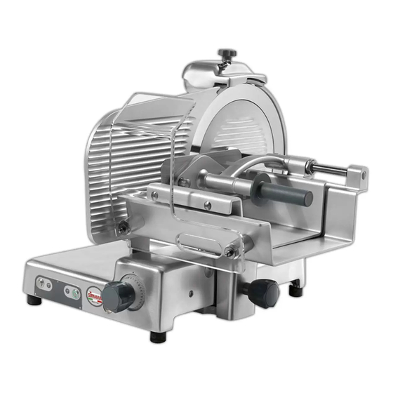
- Page 4 They should be disposed of separately and according to the norms in force in the country of installation. Dimensions Gross AxBxC weight (mm) (Kg) MNT 300 VCO 870x840x750 MNT 300 VCS 870x840x750 Fig. n°1 MNT 300 BS 870x840x750 51,5...
- Page 5 Do not expose the package to humidity or rain (Fig. n°4). Fig. n°4 Heavy package. Do not lift manually unless with help of at least three people (Fig. n°5). Fig. n°5 Move the package only by electrical trolleys manually, equipped with lifting straps (Fig.
-
Page 6: Chap. 2 - Installation
overturn the package!! When transporting it make sure that it is firmly held by the four corners (keeping it parallel to the floor). CHAP. 2 - INSTALLATION WARNING! All operations must be carried out by specialized personnel (Fig. n°9). 2.1 - UNPACKING Fig. - Page 7 2.2 - POSITIONING Position the pallet, with the slicer, on a flat surface and take off (a) the cap from the slicer (Fig. n°12). At this point turn the machine on its side (Fig. n° 13) and unscrew, with the proper wrench provided, the 4 nuts which fasten the slicer.
-
Page 8: Electrical Connection
2.3 - ELECTRICAL CONNECTION LEGEND (A) = Product code and name (B) = Power supply Check that the data reported on the (C) = Motor frequency (D) = Amperage technical-part number plate (Fig. n°18), in the (E) = Serial number (F) = Barcode delivery documents, correspond in the right order;... -
Page 9: Preliminary Check
2.3.5 - Electrical connection modification Unless otherwise specified, the slicers are equipped with 400 V. three-phase connection. To modify the connection carefully follow these instructions: - remove the plug from the electric network; - turn the slicer on the side opposite the trolley; - take off the yellow cover from the electrical box;... -
Page 10: General Precautions
CHAP. 3 - INFORMATION ON THE MACHINE 3.1 - GENERAL PRECAUTIONS The general precautions, even though they appear obvious, are fundamental for the installation, use, maintenance and possible inconveniences with their respective solutions. • The slicer is designed for cutting fresh, seasoned and cooked meats, cured meats and vegetables, non-frozen and boneless, up to maximum 20°C (Fig. -
Page 11: Construction Features
• Do not leave the slicer exposed to damaging agents: sun, rain, sprays, humidity, ice (Fig. n°28). • Do not pull the slicer or the feeding cable (Fig. n°29) to unplug it. • Regularly check the state of the feeding cable;... - Page 12 Fig. n°30 LEGEND: Ring Bladeguard tie rod hand grip Cap hand grip Thickness gauge plane Goods presser hand grip Base Sliding plate Foot Goods presser handguard Controls Plate hand grip Graduated hand grip Sliceguard Handguard Sliceguard hand grip Stem Thickness gauge plane cover Stem hand grip Thickness gauge plane cover hand grip Goods holder plate...
- Page 13 4.2 - SAFETY DEVICES INSTALLED ON THE MACHINE 4.2.1 - Mechanical safety As far as mechanical safety is concerned, the slicer described in this manual responds to: - CEE 2006/42 machine directives. Safety is made possible by the: (Fig. n°31-32) - Bladeguard (ref.
-
Page 14: Description Of The Machine
Even though the professional CE slicers are equipped with the standard mea-sures for electrical and mechanical protection (both while operating and during cleaning and maintenance), RESIDUAL RISKS which cannot be completely eliminated in any case exist, highlighted in this manual under the form of WARNING. They concern the danger of cutting, bruising and other caused by the blade or by other machine parts. - Page 15 4.4 - OVERALL DIMENSIONS, WEIGHT, FEATURES ... TAB. n°1 - DIMENSION MEASUREMENTS AND TECHNICAL FEATURES Fig. n°35 TAB. n°1 - MISURE D’INGOMBRO E CARATTERISTICHE TECNICHE MODEL MNT 300 - 330 - 350 Blade diameter 468x338 468x338 468x338 CxDxE 635x600x500 645x600x515...
- Page 16 TAB. n°2 - DIMENSION MEASUREMENTS AND TECHNICAL FEATURES MODEL U.m. MNT 300 - 330 - 350 Blade diameter 468x338 468x338 468x338 CxDxE 635x685x500 645x685x515 660x685x530 FxDxG 720x685x560 720x685x560 720x685x560 Hopper 340x250 340x250 340x250 Run of carriage X Y H W...
- Page 17 TAB. n°3 - DIMENSION MEASUREMENTS AND TECHNICAL FEATURES MODEL U.m. MNT 300 - 330 - 350 Blade diameter 468x338 468x338 468x338 CxDxE 635x652x500 645x652x515 660x652x530 FxDxG 677x652x520 677x652x520 677x652x520 Hopper 280x260 280x260 280x260 Run of carriage 260 230 260 245...
-
Page 18: Operational Check
CHAP. 5 - MACHINE USE 5.1 - OPERATIONAL CHECK Before every use, please follow these instructions: - check that installation has been carried out correctly as in chapter 2; - make sure the hand guard has been installed correctly and tightened; - check that the hopper is well fastened with the lock hand grip (Fig. -
Page 19: Loading And Cutting The Product
5.2 - LOADING AND CUTTING THE PRODUCT WARNING: The goods to be cut are loaded on the hopper only with the graduated hand grip at “0” and the motor stopped, being careful with the blade and the points. Adhere to the following procedure: Lift the goods presser, load the goods on the hopper, bringing it close to the thickness gauge, block it with theproper... -
Page 20: Sharpening The Blade
5.3 - SHARPENING THE BLADE WARNING: Before starting to sharpen the blade, pay attention to RESIDUAL RISKS (chapter 4.2.2) concerning the dangers of cutting without having followed the instructions listed below. To sharpen the blade, which needs to be done periodically as soon a decrease in cutting is noticed, the following directions must be adhered to: 1. -
Page 21: Cleaning The Machine
CHAP. 6 - ROUTINE CLEANING 6.1 - GENERALITIES • Cleaning the machine must be carried out at least once a day or, if necessary, more frequently . • All the parts of the slicer that come in direct or indirect contact with the food to be cut must be scrupulously cleaned. - Page 22 the following way: unhook the bladeguard (Fig. n°49); take out the sharpening device (Fig. n°51 ref.a) and open, by using the graduated hand grip, the thickness gauge enough to make the jig (Fig. n°51 rif.b) stick to the blade; 3. unscrew the three or four screws (Fig. n°51 ref.f), depending on the model, which fasten Fig.
-
Page 23: Chap. 7 - Maintenance
6.3 - SLIDE GUIDES LUBRICATION The slide guides on the carriage (1-2) must be lubricated periodically with the equipped oil (a). Fig. n°55 CHAP. 7 - MAINTENANCE 7.1 - GENERALITIES Before carrying out any maintenance operations it is necessary to: a) disconnect the feed plug from the electrical network to completely isolate machine from the rest of the system. -
Page 24: Chap. 8 - Dismantling
CHAP. 8 - DISMANTLING 8.1 - OUT OF SERVICE If for some reason it is decided to put the machine out of service, make sure that it cannot be used by anyone: detach or cut the electrical connections. 8.2 - WEEE Waste of Electric and Electronic Equipment Directive 2002/95/EC, 2002/96/EC and 2003/108/EC on the restriction of the use of certain hazardous substances in electrical and electronic equipment, and waste electrical and... - Page 25 CAP. 9 - ECTRICAL DIAGRAM 9.1 - 115 V. - 230V. SINGLE-PHASE - 230V. THREE-PHASE - 400V. THREE-PHASE Fig. n°56...
- Page 26 SERVICE CENTRE AUTHORISED DEALER...
Need help?
Do you have a question about the MNT 300 and is the answer not in the manual?
Questions and answers