Table of Contents
Advertisement
1
2
TUS PWR 1
3
PWR 2
4
ID
5
6
7
SET
CO NSO LE
Gre en= 100
0M Yel low
=1 0/1 00M
On =Li nk Fla
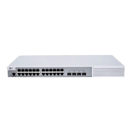
S3910 Series Switches
MANAGED L2+ GIGABIT SWITCHES
Quick Start Guide
8
9
10
11
12
13
14
15
16
17
18
19
20
21
22
23
shi ng =A CT
V1.0
S3 91 0-2 4T
S
24
25
26
27
28
29
30
31
32
33
34
35
36
37
38
39
40
41
42
43
44
45
46
47
48
SFP +
49
50
51
52
S3 91 0- 48
TS
Advertisement
Table of Contents

Related Manuals for FS S3910 Series


Summary of Contents for FS S3910 Series
- Page 1 TUS PWR 1 PWR 2 CO NSO LE Gre en= 100 0M Yel low =1 0/1 00M On =Li nk Fla shi ng =A CT SFP + S3 91 0- 48 S3910 Series Switches MANAGED L2+ GIGABIT SWITCHES Quick Start Guide V1.0...
- Page 2 Introduction Thank you for choosing S3910 Series Stackable Managed Switches. This guide is designed to familiarize you with the layout of the switch and describes how to deploy the switch in your network. S3910-24TS STATUS PWR1 PWR2 S3910-24TS SFP+ RESET...
-
Page 3: Hardware Overview
Hardware Overview Front Panel Ports S3910-24TS S3910-24TS STATUS PWR1 PWR2 SFP+ RESET CONSOLE Green=1000M Yellow=10/100M On=Link Flashing=ACT CONSOLE RJ45 SFP+ S3910-48TS SFP+ STATUS PWR1 PWR2 RESET CONSOLE Green=1000M Yellow=10/100M On=Link Flashing=ACT S3910-48TS CONSOLE RJ45 SFP+ Ports Description 10/100/1000BASE-T ports for Ethernet connection RJ45 SFP+ ports for 1/10G connection SFP+... -
Page 4: Back Panels
Back Panels S3910-24TS / S3910-48TS PWR2 PWR1 Dual Power Supplies Grounding Point Front Panel LEDs S3910-24TS STATUS PWR2 RJ45 SFP+ S3910-24TS STATUS PWR1 PWR2 SFP+ RESET CONSOLE Green=1000M Yellow=10/100M On=Link Flashing=ACT PWR1 S3910-48TS STATUS PWR2 RJ45 SFP+ STATUS PWR1 PWR2 RESET CONSOLE S3910-48TS... - Page 5 LEDs Status Description No power supply module is connected. Solid Green A power supply is connected and able to work. PWR1/PWR2 Solid Red A redundant power supply fails or no AC cable is connected. Locating is disabled. Locating is enabled. Operation and maintenance sta turn Solid Blue on and o the LED remotely.
-
Page 6: Installation Requirements
Installation Requirements Before you begin the installation, make sure that you have the following: Phillips screwdriver. Standard-sized, 19" wide rack with a minimum of 1U height available. ST AT US PW R1 PW R2 Category 5e or higher RJ-45 Ethernet cables, ber optical cables and console cable for connecting network devices. -
Page 7: Rack Mounting
Rack Mounting ST AT US PW R1 PW R2 RE SE T CO N SO LE G re en = 10 00 M Ye llo w = 10 /1 00 M O n = Li n k Fl as h in g = A C T SF P+ S 3 9 1 0 -4 8... -
Page 8: Wall Mounting
Wall Mounting SF P+ S 3 9 1 0 -4 8 S 3 9 1 0 -4 8 1. Attach the mounting brackets to the switch with the supplied screws. 2. Use the expansion screws to securely attach the mounting brackets on the wall. NOTE: Suitable for mounting on concrete or other non-combustible surface only. -
Page 9: Installing The Power Supply Module
Installing the Power Supply Module P W R 1 P W R 2 1. Take a new power module out of the package. 2. Take the plane printed with power information as the top panel of the power module. Hold the handle of the power module with one hand, and hold the end of the power module with the other hand. -
Page 10: Grounding The Switch
Grounding the Switch 1. Connect one end of the grounding cable to a proper earth ground, such as the rack in which the switch is mounted. 2. Secure the grounding lug to the grounding point on the switch back panel with the washers and screws. -
Page 11: Connecting The Sfp+ Ports
Connecting the RJ45 Ports S 3 9 0 0 -2 4 T 4 S 1. Connect an Ethernet cable to the RJ45 port of a computer, printer, network storage, or other network devices. 2. Connect the other end of the Ethernet cable to the RJ45 port of the switch. Connecting the SFP+ Ports S FP + S 3 9 1 0 -4 8... -
Page 12: Connecting The Console Port
2. Connect the DB9 female connector of the console cable to the serial port on the computer. Stacking the S3910 Series Switches The S3910 series switches support stacking up to 4 switches between the same models together. Switches in the series can be physically stacked using optical ber cables connected to SFP+ transceivers or 10G Direct Attach Cables (DAC). -
Page 13: Configuring The Switch
Configuring the Switch Configuring the Switch Using the Web-based Interface Step 1: Connect the computer to the business port of the switch using the network cable. Step 2: Set the IP address of the computer to 192.168.1.x. (“x” is any number from 2 to 254.) I nter n et Protocol Versi o n 4 ( TC P/I P v4) Prope r tie s General Yo u c a n g e t I P s e t t i n g s a s s i g n e d a u t o m a t i c a l l y i f y o u r n e t w o r k... -
Page 14: Troubleshooting
Configuring the Switch Using the Console Port Step 1: Connect a computer to the switch's console port using the console cable. Step 2: Start the terminal simulation software such as HyperTerminal on the computer. Step 3: Set the parameters of the HyperTerminal: 9600 bits per second, 8 data bits, no parity, 1 stop bit and no ow control. -
Page 15: Support And Other Resources
Contact Us Product Warranty FS ensures our customers that any damage or faulty items due to our workmanship, we will o er a free return within 30 Days from the day you receive your goods. This excludes any custom made items or tailored solutions.
Need help?
Do you have a question about the S3910 Series and is the answer not in the manual?
Questions and answers