Table of Contents
Advertisement
Quick Links
Advertisement
Table of Contents

Subscribe to Our Youtube Channel
Related Manuals for Telycam NDI HX3


Summary of Contents for Telycam NDI HX3
- Page 1 |HX3 FHD PTZ Camera ® User Manual V1.0 J.BC.0205.0183...
- Page 3 |HX3 FHD PTZ Camera ® User Manual V1.0 J.BC.0205.0183...
-
Page 5: Table Of Contents
〓〓〓〓〓〓 CONTENT 〓〓〓〓〓〓 CONTENT ......................1 SAFETY GUIDES .....................2 USE CHECK ..................... 4 PRODUCT HIGHLIGHTS ................6 CAMERA SPEC ....................7 INTERFACE DESCRIPTION ................9 CAMERA DIMENSION .................10 INSTALLATION ..................... 11 IR REMOTE CONTROLLER ................ 13 VISCA IN(RS232 PORT) ................15 VISCA PROTOCOL ..................17 PELCO-D PROTOCOL .................. -
Page 6: Safety Guides
〓〓〓〓〓 SAFETY GUIDES 〓〓〓〓〓 ● Before operation, please fully read and follow all instructions in the manual. For your safety, always keep this manual with the camera. ● The camera power voltage is 12V DC, rated currency is 2A. We suggest you use it with the original power supply adapter supplied by the factory. - Page 7 〓〓〓〓〓 SAFETY GUIDES 〓〓〓〓〓 Attention! ▲ The video quality may be affected by the specific frequencies of electromagnetic field. ▲ Never grasp the head of the camera, and never move the camera by hand when it is working, otherwise, mechanism maybe destroyed. Declaration:...
-
Page 8: Use Check
〓〓〓〓〓〓 USE CHECK 〓〓〓〓〓〓 PACKING LIST Check all below items when open the package Camera ················································· 1PCS Power Adapter········································· 1PCS Power Cable··········································· 1PCS Remote Controller···································· 1PCS USB Type-C Cable····································1PCS RS232 Cable··········································· 1PCS User Manual··········································· 1PCS QC PASS··············································· 1PCS Shock-absorbing Pad································· 1PCS QUICK START —... - Page 9 〓〓〓〓〓〓 USE CHECK 〓〓〓〓〓〓 Dial Switch Setting (at the bottom of the camera) Dial Switch (ARM) SW-1 SW-2 Instruction Upgrading mode Debugging mode Undefined Working mode Dial Switch SW-3 SW-4 Instruction Reserved Reserved Reserved Reserved Dial Switch SW-5 SW-6 Instruction Undefined Working mode Undefined...
-
Page 10: Product Highlights
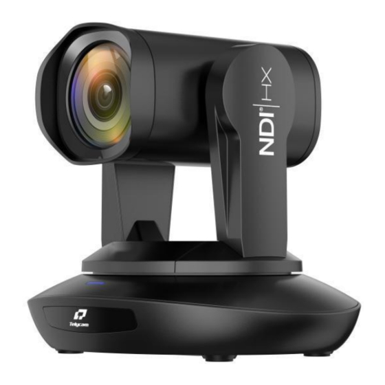
〓〓〓 PRODUCT HIGHLIGHTS 〓〓〓 ★ Adopting the most advanced image processing DSP, 1/1.8-inch 12MP sensor. ★ High-Definition Optical Lens: 30x optical zoom, with 60-degree field of view. ★FHD 1080P60 video output from NDI |HX (or Ethernet) , while supporting ® H.264, H.265 encoding. -
Page 11: Camera Spec
〓〓〓〓〓 CAMERA SPEC 〓〓〓〓〓 |HX3 FHD PTZ Camera ® Sensor 1/1.8inch high quality, 1200 MP CMOS Sensor 1920*1080P60/59.94/50/30/29.97/25/24/23.98 HDMI 1920*1080I60/59.94/50 1280*720P60/59.94/50/30/29.97/25 1920*1080P60/59.94/50/30/29.97/25/24/23.98 1920*1080I60/59.94/50 1280*720P60/59.94/50/30/29.97/25 Video Format MJPG, H.264, HEVC: 3840*2160P30; 1920*1080P60; 1280*720P60; 1024*576P60; 800*448P60 NV12, YUY2: 1920*1080P5; 1280*720P15; 1024*576P25; 800*448P30 1920*1080P15~60;... - Page 12 〓〓〓〓〓 CAMERA SPEC 〓〓〓〓〓 POE+ Supported Daisy Chain Support RS232 serial daisy chain Minimum Lux 0.01lux White Balance Auto / Manual / ATW / Push / Indoor / Outdoor / Color Temperature Exposure Auto / Manual / Iris / Bright Focus Auto / Manual Iris...
-
Page 13: Interface Description
〓〓 INTERFACE DESCRIPTION 〓〓 1.Camera Lens 6.Tripod Screw Hole 11.USB Type-C port 2.Camera Base 7.Installation Hole 12.HDMI port 3.IR Receiver Panel 8.RS232 ((IN) port 13.3G-SDI port 4.Power Indicator Light 9.RS232 (OUT) port port ® 5.Dial Switch 10.Line in port 15.DC 12V plug —... -
Page 14: Camera Dimension
〓〓〓〓 CAMERA DIMENSION 〓〓〓〓 — 10 —... -
Page 15: Installation
〓〓〓〓〓 INSTALLATION 〓〓〓〓〓 Wall-Mount Installation: 1.Drill the hole on the wall referring to the wall mounting bracket hole position, hole diameter of φ6mm, position the four φ6mm plastic expansion screws in the drilled hole. 2.Use four M4*30 self-tapping screws to mount the wall-mount bracket on the wall. - Page 16 〓〓〓〓〓 INSTALLATION 〓〓〓〓〓 Ceiling-Mount Installation : 1.Referring to the position of the cover plate holes on the bracket in the concrete ceiling, drill a hole of φ6, and position 3 plastic expansion screws of φ6 in the hole. 2.Use three M4*30 self-tapping screws to mount the bracket the upper cover plate on the ceiling.
-
Page 17: Ir Remote Controller
〓〓 IR REMOTE CONTROLLER 〓〓 POWER Short press POWER key to enter standby mode from normal working mode. Press it again, the camera will do self-checking, then go back to HOME position. It will go to preset position if power on mode has been set before. FREEZE Short press FREEZE key to freeze/unfreeze the image. - Page 18 〓〓 IR REMOTE CONTROLLER 〓〓 CLR PRE (CLEAR PRESET) CLR PRE+number key:to clear the relative preset. Long press to clear all presets. FOCUS KEY: +/- Manual focus, only valid under manual focus mode. ZOOM KEY: +/- Set the Zoom rate. NAVIGATE KEY:UP/DOWN/LEFT/RIGHT Under working mode, use navigate key to set the pan tilt, and select menu when enter OSD.
-
Page 19: Visca In(Rs232 Port)
〓〓〓 VISCA IN (RS232 PORT) 〓〓〓 V_IN V_OUT V_IN RS485 A(+) B(-) VISCA IN 与 Mini DIN VISCA IN 与 DB9 Connection Connection CameraVISCA IN Windows DB-9 Camera VISCA IN Mini DIN A(+) A(+) IR OUT IR OUT B(-) B(-) —... - Page 20 〓〓〓 VISCA IN (RS232 PORT) 〓〓〓 VISCA Network Construction: SERIAL PORT CONFIGURATION: Parameter Value Baud rate 2400/4800/9600/115200 Start bit 1bit Date bit 8bits Stop bit 1bit Check bit 无 — 16 —...
-
Page 21: Visca Protocol
〓〓〓〓 VISCA PROTOCOL 〓〓〓〓 Part1 Camera Return Command Ack/Completion Message command Note z0 41 FF Returned when the command is accepted. Completion z0 51 FF Returned when the command has been executed. Error Messages command Note Returned when the command format is different or when a Syntax Error z0 60 02 FF command with illegal command parameters is accepted. - Page 22 〓〓〓〓 VISCA PROTOCOL 〓〓〓〓 Command type function command Direct 8x 01 04 46 0p 0q 0r 0s FF Enable In separate mode Stop 8x 01 04 08 00 FF Far(Standard) 8x 01 04 08 02 FF Near(Standard) 8x 01 04 08 03 FF Far (Variable) 8x 01 04 08 2p FF p=0 (Low) to 7 (High)
- Page 23 〓〓〓〓 VISCA PROTOCOL 〓〓〓〓 Command type function command Bright Mode (Manual Bright 8x 01 04 39 0D FF control) Reset 8x 01 04 0A 00 FF 8x 01 04 0A 02 FF Shutter Setting CAM_Shutter Down 8x 01 04 0A 03 FF pq: Shutter Position Direct 8x 01 04 4A 00 00 0p 0q FF...
- Page 24 〓〓〓〓 VISCA PROTOCOL 〓〓〓〓 Command type function command 8x 01 04 61 02 FF Image Flip Horizontal CAM_LR_Reverse ON/OFF 8x 01 04 61 03 FF 8x 01 04 66 02 FF Image Flip Vertical CAM_Picture Flip ON/OFF 8x 01 04 66 03 FF 8x 01 06 A5 02 FF CAM_RS485Ctl 8x 01 06 A5 03 FF...
- Page 25 〓〓〓〓 VISCA PROTOCOL 〓〓〓〓 Command type function command pp: Video format 1080P60 0x00 1080P50 0x01 1080I60 0x02 1080I50 0x03 1080P30 0x04 1080P25 0x05 720P60 0x06 Video System 720P50 0x07 8x 01 06 35 00 pp FF Set(Factory) 720P30 0x08 720P25 0x09 1080P5994 0x0E...
- Page 26 〓〓〓〓 VISCA PROTOCOL 〓〓〓〓 Command type function command pqrs : Column(x size) mnxy: Line (y size) 8x 01 04 C2 00 0p 0q 0r 0s 0m only support: resolution 0n 0x 0y FF 1920*1080 1280*720 1024*576 8x 01 04 C2 01 0p 0q 0r 0s 0m pqrsmnxy: bitrate rate 0n 0x 0y FF...
- Page 27 〓〓〓〓 VISCA PROTOCOL 〓〓〓〓 Command type function command P=0: OFF P=1: RED P=2: GREEN P=3: RED&GREEN Cam_Tally 8x 01 7E 01 0A 00 0p FF P=4: BLUE P=5: RED&BLUE P=6: GREEN&BLUE P=7: RED&GREEN&BLUE 8x 01 06 01 VV WW 03 01 FF Down 8x 01 06 01 VV WW 03 02 FF Left...
- Page 28 〓〓〓〓 VISCA PROTOCOL 〓〓〓〓 Command type command return note CAM_PT Speed Inq(IR) 8x 09 04 C1 FF y0 50 pp FF pp: 0x05~0x18 CAM_Zoom Speed 8x 09 04 D1 FF y0 50 0p FF p:0x00~0x07 Inq(IR) y0 50 02 FF Auto Focus CAM_Focus Mode Inq 8x 09 04 38 FF...
- Page 29 〓〓〓〓 VISCA PROTOCOL 〓〓〓〓 Command type command return note CAM_ Bright Posi Inq 8x 09 04 4D FF y0 50 00 00 0p 0q FF pq: Bright Position y0 50 02 FF CAM_WDR Mode Inq 8x 09 04 3D FF y0 50 03 FF CAM_WDR Pos Inq 8x 09 04 D3 FF...
- Page 30 〓〓〓〓 VISCA PROTOCOL 〓〓〓〓 Command type command return note CAM_Flare Green 8x 09 04 B9 FF y0 50 pp FF CAM_Flare Blue 8x 09 04 BA FF y0 50 pp FF y0 50 ab cd mn pq rs tu vw CAM_Version Inq 8x 09 00 02 FF Video System...
- Page 31 〓〓〓〓 VISCA PROTOCOL 〓〓〓〓 Command type command return note pqrs : Column(x size) Sub stream Resolution 8x 09 04 C3 00 y0 50 0p 0q 0r 0s 0m 0n 0x mnxy: Line (y size) 0y FF only support: 640*360 8x 09 04 C3 01 y0 50 0p 0q 0r 0s 0m 0n 0x pqrsmnxy: bitrate Sub stream Rate Inq...
- Page 32 〓〓〓〓 VISCA PROTOCOL 〓〓〓〓 VISCA PAN TILT ABSOLUTE POSITION VALUE PAN ANGLE VISCA value TILT ANGLE VISCA value -170 0xF670 0xFE50 -135 0xF868 0x0000 0xFAF0 0x01B0 0xFD78 0x0360 0x0000 0x510 0x0288 0x0510 0x0798 0x0990 VISCA PAN TILT SPEED VALUE Pan(Degree/Second) Tilt(Degree/Second) —...
-
Page 33: Pelco-D Protocol
〓〓〓〓 PELCO-D PROTOCOL 〓〓〓〓 Function Byte1 Byte2 Byte3 Byte4 Byte5 Byte6 Byte7 0xFF Address 0x00 0x08 Pan Speed Tilt Speed Down 0xFF Address 0x00 0x10 Pan Speed Tilt Speed Left 0xFF Address 0x00 0x04 Pan Speed Tilt Speed Right 0xFF Address 0x00 0x02... -
Page 34: Pelco-P Protocol
〓〓〓〓 PELCO-P PROTOCOL 〓〓〓〓 Function Byte1 Byte2 Byte3 Byte4 Byte5 Byte6 Byte7 Byte8 Tilt 0Xa0 Address 0x00 0x08 Pan Speed 0Xaf Speed Tilt Down 0Xa0 Address 0x00 0x10 Pan Speed 0Xaf Speed Tilt Left 0Xa0 Address 0x00 0x04 Pan Speed 0Xaf Speed Tilt... -
Page 35: Osd Menu
〓〓〓〓〓〓 OSD MENU 〓〓〓〓〓〓 1. Under working mode, press the MENU key on the IR remote controller, to enter the OSD menu as bellow: 2. After entering the main menu, use the navigate UP/DOWN key to select the main menu. Once selected, the main menu will change to blue background, and the right side will show sub-menu options. - Page 36 〓〓〓〓〓〓 OSD MENU 〓〓〓〓〓〓 Iris setting: CLOSE~F1.8, only valid under IRIS Default: AUTO MANUAL and IRIS mode Gain setting: 0dB~30dB, only valid under GAIN Default: AUTO MANUAL mode EXPOSURE Bright setting: 0~27, only valid under Default: AUTO BRIGHT BRIGHT priority mode. BRIGHT 0~15 Default: 8...
- Page 37 〓〓〓〓〓〓 OSD MENU 〓〓〓〓〓〓 MIRROR Flip vertical Default: OFF PT SPEED Set Pan Tilt speed: 5~24 Default: 18 ZOOM SPEED Set Zoom speed: 1~7 Default: 5 PRESET PT Preset head speed:2~24 Default: 18 SPEED PRESET ZOOM Preset zoom speed:1~7 Default: 5 SPEED PRESET SAVE Optional: OFF, ON...
- Page 38 〓〓〓〓〓〓 OSD MENU 〓〓〓〓〓〓 Set IP Address in Menu In order to help customer debugging, the camera has the support menu to set IP address. The specific methods are as follows. 1. Press "MENU" to open the menu interface, and select "network parameters" in the menu to call up the IP setting interface.
-
Page 39: Uvc Control
〓〓〓〓〓 UVC CONTROL 〓〓〓〓〓 1. Only run the client software after the camera has completed self-configuration (the IR indicator in blue color and will not flick; otherwise it may cause black screen issue. 2. Make sure the camera is recognized by the PC Device Manager. 3. -
Page 40: Web Setting
〓〓〓〓〓 WEB SETTING 〓〓〓〓〓 It is not necessary to install an additional video player plug-in to preview the local screen on the web interface. The web interface supports Google Chrome, Firefox, IE, Safari, Opera, 360, QQ and other browsers, adaptability is very good. 1. - Page 41 〓〓〓〓〓 WEB SETTING 〓〓〓〓〓 3. Parameter Setting Click “Setting” to enter into the parameter setting interface as follows: “Video Encode”: can set image encode mode, main stream and sub stream resolution/bit rate/frame rate, bit rate control way, and I frame interval etc as above image.
- Page 42 〓〓〓〓〓 WEB SETTING 〓〓〓〓〓 “Video Transmission”: RTMP, NDI and SRT settings are available, as shown in the following figure: "Audio Settings": the audio enable can be off / on, the encoding mode can be selected, and the parameters such as sampling rate and bit rate can be adjusted, as shown in the following figure: “Image Parameter”...
- Page 43 〓〓〓〓〓 WEB SETTING 〓〓〓〓〓 Focus including focus mode, default focal distance, digital zoom etc. Exposure includes exposure mode, shutter speed, gain, iris, brightness, and anti-flicker. White Balance includes white balance mode, red gain, blue gain. Image includes mirror, flip, backlight compensation, Gamma, WDR(wide dynamic range).
- Page 44 〓〓〓〓〓 WEB SETTING 〓〓〓〓〓 Noise reduction includes 2D/3D reduction. There is on/off option for 2D, and off/auto/1~4 six options for 3D. Digital Output option sets the resolution of the camera's HDMI and SDI images. “Ethernet” includes DHCP mode, IP address, Netmask, Gateway, Http Port, RTSP Port, VISCA Over IP.
- Page 45 〓〓〓〓〓 WEB SETTING 〓〓〓〓〓 “Reset Options”: reset the camera to the default setting Reset: reset camera image parameter Reset/Reboot: reset camera Ethernet and image parameter, language and protocol will not be reset. Reboot: Reboot ISP part of camera. “Account Setting”: is used for setting the camera account and password Input the account firstly, then input the same password twice, and click set to finish.
-
Page 46: View Rtsp Video Via Vlc
〓〓 VIEW RTSP VIDEO VIA VLC 〓〓 Default RTSP main streaming address: rtsp://192.168.1.188/stream/main Default RTSP sub streaming address: rtsp://192.168.1.188/stream/sub Default RTMP main streaming address: rtmp://192.168.1.188:1935/app/rtmpstream0 Default RTMP sub streaming address: rtmp://192.168.1.188:1935/app/rtmpstream1 1. Run VLC Media Player. 2. Media->network stream, to enter into “open media” interface. 3. -
Page 47: Ndi Tools
〓〓〓〓〓 NDI Tools Guide 〓〓〓〓〓 1. Image Preview https://ndi.tv/tools/ A. Download the NDI Tools via and install it. B. Find out the NDI 5 Tools/Studio Monitor via Windows toolbars, and then open it, as below: C. Right-click on the Studio Monitor screen, and select the preview device: 2. - Page 48 〓〓〓〓〓 NDI Tools Guide 〓〓〓〓〓 Refer to the above picture, once open the video via Studio Monitor, there will show up a setting icon in the lower right corner, single click this icon to enter WEB UI. 4. How to use NDI tools to Virtual Input CAMERA A.
-
Page 49: Visca Over Ip
〓〓〓〓〓〓 VISCA over IP 〓〓〓〓〓〓 VISCA over IP: VISCA over IP means VISCA protocol transmit via IP, to reduce RS232/RS485 cable layout (the controller must support IP communication function) Communication port spec: Control port: RJ45 Gigabit LAN IP protocol: IPv4 ... - Page 50 〓〓〓〓〓〓 VISCA over IP 〓〓〓〓〓〓 Command format: the following is the message head and valid message format. Note: LAN output way is big-endian, LSB is in the front. Payload type: Data definition as following: Value Value Name Value (Byte 0) (Byte1) VISCA command 0x01...
- Page 51 〓〓〓〓〓〓 VISCA over IP 〓〓〓〓〓〓 sequence number becomes the max value, it will change to 0 for the next time. The peripheral equipment will save the sequence number of each command, and return the sequence number to the controller. Payload According to the Payload type, the following data will be saved.
- Page 52 〓〓〓〓〓〓 VISCA over IP 〓〓〓〓〓〓 delivery and resent in the application. Generally, when the controller sends a command to peripheral equipment, the controller will wait for the return message and then send the next command, we can detect and confirm if the peripheral equipment receives the commands from the return message’s lag time.
- Page 53 〓〓〓〓〓〓 VISCA over IP 〓〓〓〓〓〓 Sequence chart as following Sequence chart when command lost Sequence chart when returned message lost Note: Do not set the IP address, subnet mask, or gateway parameter in VISCA over IP command, otherwise, it will cause the network breaks off. Due to change these parameters, the network will be in off status.
- Page 58 Telecam Technology Co.,Ltd Add: 3F, 6F, 7F, Building A, Shuanghuan Information Technology Industrial Park, No.8, Baoqing Rd, Longgang District, Shenzhen, 518116, China Tel: +86-755-33275155 Website: Https://www.telycam.com E-mail: telycam@telycam.com...
Need help?
Do you have a question about the NDI HX3 and is the answer not in the manual?
Questions and answers