
Subscribe to Our Youtube Channel
Related Manuals for Farmi Forest CH18 PTO


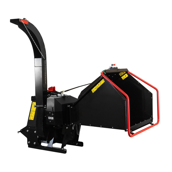
Summary of Contents for Farmi Forest CH18 PTO
- Page 1 CHIPPER CH18 PTO OPERATION AND MAINTENANCE MANUAL PLEASE READ THE OPERATING AND MAINTENANCE INSTRUCTIONS BEFORE YOU OPERATE THE MACHINE FROM MACHINE: 300000344 INSTRUCTION MANUAL A-EN-300000344-CS CH18...
-
Page 3: Table Of Contents
TABLE OF CONTENTS INTRODUCTION ......................................6 PRODUCT WARRANTY ....................................6 GENERAL SAFETY INSTRUCTIONS ................................7 STARTING ......................................... 7 TRANSPORT ......................................8 OPERATION ......................................8 MAINTENANCE ......................................9 OILS AND LUBRICATION ................................... 9 SAFETY INSTRUCTIONS FOR HYDRAULIC CIRCUITS ..........................10 GENERAL SAFETY INSTRUCTIONS FOR THE CHIPPER ..........................10 CH18 –... - Page 5 EC DECLARATION OF CONFORMITY Original declaration of conformity Manufacturer: Farmi Forest Corporation Kilpivirrantie 7, FIN-74120 IISALMI, Finland Person authorized to compile the technical documentation: Name: Petri Pelkonen Address: Kilpivirrantie 7, FIN-74120 IISALMI, Finland Commercial name: Farmi Machine denomination: Farmi wood chipper with attachable Farmi feed hopper...
-
Page 6: Introduction
INTRODUCTION This manual includes the information and maintenance instructions required for operating the attachment in the optimal manner. Although you have experience in using this kind of attachmentry, read the operation and maintenance instructions carefully since they include information enabling efficient and safe operation. Regular maintenance is the best way to guarantee the efficient and economical performance of the attachment. -
Page 7: General Safety Instructions
GENERAL SAFETY INSTRUCTIONS These safety instructions are meant for the owners of FARMI attachment, as well as those who operate, service or repair it. The instructions help with: 1. using the attachment safely, appropriately, and effectively. 2. identifying, avoiding, and preventing potentially dangerous situations. The manufacturer supplies an operation manual, which must always be available at the place of operation of the attachment. -
Page 8: Transport
6. Wear all necessary safety equipment; eye protection goggles, hearing protection or ear plugs, and use only close fitting gloves. 7. Never wear loose clothing around moving parts. Protect long hair! 8. Ensure that work is carried out according to the stipulations of applicable occupational health and safety legislation. -
Page 9: Maintenance
2. Also check the universal joint’s safety equipment and joints. 3. Never insert any body part into the attachment with the engine running. 4. If any faults arise that may jeopardize occupational safety, turn off the attachment. 5. During operation, the attachment’s operator is responsible for safety in the whole work area. Work may not be carried out in the presence of any factors that jeopardize occupational safety. -
Page 10: Safety Instructions For Hydraulic Circuits
SAFETY INSTRUCTIONS FOR HYDRAULIC CIRCUITS 1. Work on hydraulic equipment may only be carried out by professional hydraulic engineers. 2. Be cautious when using the equipment in cold conditions. 3. Check the attachment for leaks. Do not use the attachment if there is a leak from any system. Check all hydraulic hoses –... - Page 11 6. As compared to the tractor, the chipper must not be lowered excessively. 7. It is not permitted to operate the chipper without feed unit or feed hopper. 8. The material to be chipped must never be fed into a crane fed chipper manually. 9.
- Page 12 STICKERS AND PLATES These plates and stickers must be found on the chipper. Replace missing plates or stickers immediately. CH18...
- Page 13 1. [40147040] 4 pcs Crushing hazard! Cutting hazard! Do not climb into the feed hopper 2. [40147010] 1 pc Cutting hazard! 3. [40147060] 1 pc MAXIMUM Hydraulic pressure 200 bar 4. [40147080] 2 pcs Stop directions 5. [41015690] 2 pcs Note! Stand on the left side of feeder.
- Page 14 7. [40147000] 1 pc DANGER! Before operation, mount the chipper to the 3- point hitch of the tractor DANGER! Before maintenance and repair, please turn off the tractor and disconnect the PTO drive shaft. DANGER! Before detaching the chipper from the tractor, it must be placed on a level surface.
-
Page 15: Ch18 - General Description And Intended Use
CH18 – GENERAL DESCRIPTION AND INTENDED USE FARMI CH18 is a disk chipper for tractor-mounted operation. The chipper can be used e.g. for the production of chips to be used for landscaping or for bio energy. The chipper can be used to chop trunks, twigs and tree tops as well as chopping waste and saw mill waste. - Page 16 DIMENSIONS CH18 TECHNICAL DATA CH 18 Type disc chipper Output < 6 m3/h Chip length 10 mm Max. wood diameter 180 mm Oil demand (175 bar) 60 l/min 540 or 1000 rpm Number of knives 4 pcs Power source hydraulics Chipper weight 405 kg Disc diameter...
- Page 17 LIFTING Lifting points for each attachment are marked with hook symbols. DANGER Lift only using the proper type of lifting device and ensure that it has an appropriate lifting capacity. Check the lifting slings, cables, and chains regularly. Ensure that you know the weight of the load to be lifted and never exceed the lifting capacity stated by the manufacturer of the lifting device.
-
Page 18: Lowering The Feed Chute Into Working Position
LOWERING THE FEED CHUTE INTO WORKING POSITION Check, that winch hook is attached to chipper. Lower the feed chute down using the winch Lock the feed chute into working position with latch. CH18... -
Page 19: Turning The Discharge Pipe
TURNING THE DISCHARGE PIPE 1. Loosen the M16 wing nut and then turn discharge pipe into wanted position. Tighten the wing nut. 2. If quide screws and nuts are too tight, the discharge pipe does not turn easily. Open M10 nut and adjust M10x50 screw. -
Page 20: Assembling The Attachment
ASSEMBLING THE ATTACHMENT Attaching the attachment to the tractor is quick and easy, but it must be done carefully. The attachment is mounted to the tractor by using the CAT I or CAT II three-point linkage. If the attachment is not locked to the tractor, it may detach from the tractor and cause a hazardous situation. The tractor must not be driven when the attachment has not been locked. -
Page 21: Pre-Operation Inspections
PRE-OPERATION INSPECTIONS 1. Make sure all protective and safety devices of the chipper are installed. Never remove any protective device during operation. 2. Before operation, please make sure there are no foreign objects in the feeder. 3. Before operation, please make sure there are no foreign objects in the chipper. 4. -
Page 22: The Operating Switch
THE OPERATING SWITCH Hydraulic feeder is operated by switch, which is located on the top of the feed chute next to emergency stop button. SETTING THE FEEDER SPEED IF NEEDED Do not set the feeder speed when the feed rollers are revolving. This damages the valve. -
Page 23: Smart Feed Basic Operating Instructions
SMART FEED BASIC OPERATING INSTRUCTIONS DESCRIPTION OF SMART FEED SYSTEM Farmi Smart Feed –control controls the rotating speed of chipper’s knife disc. Rotating speed varies during chip- ping, depending on load. Smart Feed controls feeding and reversing on the basis of rotating speed information. By controlling the feed rollers Smart Feed aims to keep knife disc rotating speed as constant as possible. - Page 24 SMART FEED BASIC M Part Order no. Product Remarks 200004498 WIRING HARNESS, CABIN 2 With control box and selector switch 200004499 WIRING HARNESS, CHIPPER SIDE Without sensors 200004408 PULSE SENSOR No stress sensor 200004409 PRESSURE SENSOR 200004500 CONTROL MODULE 200004501 LIMIT SWITCH 200004415 EMERGENCY STOP PUSH BUTTON STARTING THE CHIPPER EQUIPPED WITH SMART FEED SYSTEM 1.
-
Page 25: Emptying The Chipper After Use
EMPTYING THE CHIPPER AFTER USE Let the chipper run empty by operating it for a short time. SWIVELING THE FEEDER TO THE TRANSPORT / STORAGING POSITION 1. Open the latch located under the feed chute. 2. Check, that winch hook is attached to the chipper 3. -
Page 26: Storage Of The Chipper
STORAGE OF THE CHIPPER Before detaching the chipper from the power source, park it on level and hard ground. Take appropriate measures to prevent the chipper from moving or falling. If the chipper is to be stored for a long period, lub- ricate the knives e.g. with petroleum jelly. Take appropriate measures to keep the water draina- ge holes on the lower chamber open. -
Page 27: Sharpening Cutting Knives
Remove knife screws A (8 pcs) and lock washers E & D (4 pcs each). Remove knife F. Sharpen or replace the knife. Mount the knife with screws and lock washers. Sharpen knives in pairs to keep lengths the same and maintain disk balance. -
Page 28: Anvil Maintenance
Final grinding of the knife ANVIL MAINTENANCE The anvils can be turned before being replaced with new ones. CH18... - Page 29 Always keep sharp edge of the anvils as a counter blade towards cutting blades to ensure low fuel consumption and safety chipping operation. CH18...
-
Page 30: Troubleshooting - Green Light
TROUBLESHOOTING – GREEN LIGHT GREEN INDICATOR LIGHT MEANINGS, SMART FEED CONTROL SYSTEM NUMBER OF BLINKS MEANING Green indicator light is not on. Control system is not on or is not receiving electricity. Possible causes of fault: 2 Blinks – Sensor fault •... -
Page 31: Troubleshooting - Red Light
TROUBLESHOOTING – RED LIGHT RED INDICATOR LIGHT MEANINGS, SMART FEED CONTROL SYSTEM NUMBER OF BLINKS MEANING Red indicator light is not on. No fault 1 Blink – Input fault Fault in limit switch, wiring or control unit input 2 Blinks – Output fault Fault in dump valve or feed valve, wiring or control unit output 3 Blinks –... -
Page 32: Other Indicator Lights
OTHER INDICATOR LIGHTS GREEN INDICATOR LIGHT MEANINGS, SMART FEED CONTROL SYSTEM NUMBER OF BLINKS MEANING The light is on continuously Normal status Continuous feed forward has been activated. Switch can be released. Setting the normal speed of the knife disc The light blinks once every second –... -
Page 33: Spare Parts
SPARE PARTS MECHANICAL MODULE CH18... - Page 34 MECHANICAL MODULE CH18...
- Page 35 MECHANICAL MODULE Part Order no. Product 200006185 DRAW BEAM, 437x800x905mm, CH18 PTO 43511780 SHELTER, 150x210x210mm 43620980 FASTENING FLAT BAR, 17X53X65MM, S=3MM 53804135 CARABINER, 6X60, DIN 5299C 54826227 KNOT CHAIN, D3, DIN 5686, ZINC, 0.8M HEX SCREW, M8x20, 8.8ZN, DIN 933 WASHER, M8, 5.8ZN, DIN 126...
- Page 36 HYDRAULIC/ELECTRICAL MODULE CH18...
- Page 37 HYDRAULIC/ELECTRICAL MODULE Part Order no. Product 200006127 HOSE ASSEMBLY, QUICK COUPLING MALE, CH18 PTO 200006026 HOSE ASSEMBLY, ID3/8"(EN857 2SC), 3/8"BSP(internal, 90deg)- 3/8"BSP(internal, straight), L=0,65m 56013246 NON-RETURN VALVE, HSB 13-CV08 200006121 WIRING HARNESS, SMART FEED BASIC M, CABIN WIRING CH18...
- Page 38 CHIPPER CH18...
- Page 39 FLANGE, D60-4MM, AKSELI, PÄÄTY HEX SCREW, M10x25, 8.8ZN, DIN 933 43620660 BEARING UNIT, PAIR, CH10, CH18, CH100, CH160, Farmi Forest LOCK WASHER, M12/25,4 SP, ZN, NORD-LOCK, DIN25201 LOCK WASHER, M10, ZN, NORD-LOCK, DIN 25201 HEX SCREW, M12x200, ST8.8ZN, DIN 931 HEX SCREW, M12x70, 8.8ZN, DIN 931...
- Page 40 FEED CHUTE CH18...
- Page 41 FEED CHUTE CH18...
- Page 42 FEED CHUTE Part Order no. Product LOCK NUT, M10, 8.8ZN, DIN 985 200001818 WINCH, 550kg, WITH 7,5MX50MM BELT, STRONGLINE X009142C 94613098 EXTENSION SPRING, DU23 DL3,5 L200 6 (TOTAL) 200006105 SAFETY BAR, 521x940x1242mm, D=32MM, CH18 HEX SOCKET CAP SCREW, M8x10, DIN912, ZN PHILLIPS HEAD SCREW, M6x10, DIN7985, 5.8ZN 10 (TOTAL) 200003698 PIPE HOLDER, 533,7, STAUFF PP.
- Page 43 FEEDER CH18...
- Page 44 FEEDER Part Order no. Product 200001727 JOINT END, TSF12 ISB LOCK SCREW, M12x35, 8.8ZN, DIN 603 19 (TOTAL) 200006063 AXLE, D20/40-282MM, CH18 200003437 FLANGED BEARING, UCF 204 HEX SCREW, M20x320, 8,8ZN, DIN931 HEX SOCKET CAP SCREW, M12x40, DIN7991 94613098 EXTENSION SPRING, DU23 DL3,5 L200 6 (TOTAL) HEX SCREW, M12x80, 8.8ZN, DIN 933 200006047 FEED ROLLER, D230, L=190MM, CH18...
- Page 45 CHIPPER CH18...
- Page 46 CHIPPER Part Order no. Product 200006113 COVER PLATE, 246x284x310MM, S=1MM, CH18 200002154 HANDLE, 300000KR 200006112 COVER PLATE, 156x228x415MM, S=1MM, CH18 200006004 PROTECTION COVER, CH18 PHILLIPS HEAD SCREW, M6x10, DIN7985, 5.8ZN 10 (TOTAL) LOCK WASHER, M8, ZN, NORD-LOCK, DIN 25201 200004875 FASTENER, GRAYSTON GE53B, TWO PAIRS IN LOOSE POLY BAG CH18...
- Page 47 CHIPPER CH18...
- Page 48 CHIPPER CH18...
- Page 49 CH18...
- Page 50 CHIPPER Part Order no. Product LOCK NUT, M12, 8.8ZN, DIN 985 16 (TOTAL) LOCK WASHER, M12, ZN, NORD-LOCK, DIN 25201 200006114 COVER PLATE, 55x448x492MM, S=3MM, CH18 LOCK SCREW, M12x35, 8.8ZN, DIN 603 19 (TOTAL) 200006120 WIRING HARNESS, SMART FEED BASIC M, CHIPPER WIRING 200006141 COVER PLATE, 125x180x252MM, S=1MM 200004906 FLOW CONTROL VALVE, DANA, RFP03 200006139 VALVE ASSEMBLY, BREVINI CH18, CETOPS AND BASE, WITHOUT...
-
Page 51: Warranty
WARRANTY Farmi Forest Oy grants a 12-month warranty on all of its products, covering material and manufacturing faults. The warranty comes into effect on the product’s delivery date. The manufacturer is not liable for damages caused by: • misuse of the product •... - Page 52 Farmi Forest Kilpivirrantie 7 74120 IISALMI FINLAND...
Need help?
Do you have a question about the CH18 PTO and is the answer not in the manual?
Questions and answers