Table of Contents
Advertisement
Advertisement
Table of Contents

Related Manuals for Midland MicroMobile MXT575


Summary of Contents for Midland MicroMobile MXT575
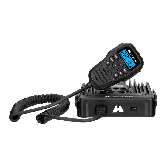
- Page 1 MXT575...
-
Page 2: Table Of Contents
Model MXT575 TABLE OF CONTENTS WELCOME TO THE WORLD OF MIDLAND......…………………………………..…….3 FEATURES....………………………………………………………………………………………..3 FCC NOTICE....……………………..…………….……………………………………………..…..4 Exposure to Radio Frequency Energy....………..……………………………………………..4 INSTALLING YOUR RADIO....………………………………………………………………….…...5 Preparation for Installation.....…..…………………………………………..5 Installing the Mounting Bracket.....…...…………………………………………..6 Installing the Antenna.....……………….………………………………………….7 Connecting the Radio to a Power source....…………………………………..8 Connecting the Microphone.....…………….……………………………………..8 Using an External Speaker....……………….…………………………………...8... -
Page 3: Welcome To The World Of Midland
Model MXT575 WELCOME TO THE WORLD OF MIDLAND RADIO Congratulations on your purchase of a high-quality Midland product. Your MXT575 2-way radio represents state-of-the-art high-tech engineering. Designed for General Mobile Radio Service (GMRS) operation, this compact package is big on performance. It is a quality piece of electronic equipment, skillfully constructed with the finest components. -
Page 4: Fcc Notice
This device complies with Part 15 of the FCC rules. Operation is subject to the condition that this device does not cause harmful interference Exposure To Radio Frequency Energy Your Midland radio is designed to comply with the following national and international standards and guidelines regarding exposure of human beings to radio frequency electromagnetic energy: •... -
Page 5: Installing Your Radio
Model MXT575 INSTALLING YOUR RADIO Preparation for Installation This radio may be installed in any 12-volt negative ground system vehicle. Most current U.S. and foreign vehicles use a negative ground system, but some older models and some newer large trucks may have a positive ground. -
Page 6: Installing The Mounting Bracket
Model MXT575 INSTALLING THE MOUNTING BRACKET 1. Using the mounting bracket as a template, mark the location of each screw hole under the dash. Use a nail or other sharp pointed object to mark the hole locations. 2. Attach the bracket to the dash with the Phillips head sheet metal screws provided. -
Page 7: Installing The Antenna
Model MXT575 INSTALLING THE ANTENNA An external antenna (50Ω) is required for the MXT575. The antenna is intended to be attached to the vehicle’s roof, trunk or similar location. Specific installation requirements vary between vehicles. Use the following guidelines to install the antenna: *Where you locate your antenna affects performance.* 1. -
Page 8: Connecting The Radio To A Power Source
Model MXT575 CONNECTING THE RADIO TO A POWER SOURCE 1. Connect the positive lead (RED wire with in-line fuse holder) to either (a) the fuse block or (b) directly to the positive post of the vehicle’s battery. NOTE: The fuse block is usually the most convenient connection point. The power cord positive lead can also be connected to the Accessory terminal on the fuse block or ignition switch, so the radio automatically turns off when the ignition is turned off. -
Page 9: Controls And Indicators
Model MXT575 CONTROLS AND INDICATORS MICROPHONE CONTROLS 1. LCD Display 2. Speaker Mic Jack 3. Menu Button 4. Call Button 5. Volume Buttons 6. Lock Button 7. Microphone 8. WX Button 9. Monitor Button 10. Scan Button 11. Transmit / Receive Indicator 12. -
Page 10: Front Panel Connections
Model MXT575 FRONT PANEL CONNECTIONS 1. Microphone Jack 2. USB-C Port Page 10 midlandusa.com... -
Page 11: Rear Panel Connections
Model MXT575 REAR PANEL CONNECTIONS 1. Antenna Jack 2. External Speaker Jack 3. Intercom Jack Page 11 midlandusa.com... -
Page 12: Lcd Display
Model MXT575 LCD DISPLAY 1. Channel Icon - Shows the selected transmit/receive channel. Receiving Icon - Indicates the radio is receiving a transmission from another user. Repeater Icon - Indicates the channel is configured to operate through a repeater. Transmitting Icon - Indicates the radio is transmitting to another user. -
Page 13: Operating Your Radio
Model MXT575 OPERATING YOUR RADIO About Range Your MXT575 is designed to give you maximum operating range under optimal conditions. Maximum Range / No Sight Obstruction Medium Range / Partial Obstruction to Line of Sight Short Range / Major Obstruction to Line of Sight Optimal conditions for maximum operating range are: •... -
Page 14: Power On/Off
Model MXT575 POWER ON/OFF 1.To power on, press and hold the POWER button for two seconds. You will hear a tone when the radio is on. • The LCD display will show all icons for one second and then display the most recently selected channel. -
Page 15: Transmit And Receiving A Call
Model MXT575 TRANSMITTING AND RECEIVING A CALL IMPORTANT! To communicate between two MXT575 radios or any GMRS radio, both radios must be set to the same channel and privacy code (see Selecting a Privacy Code) selections.. 1.To transmit a call, press and hold the PTT button on the microphone, and speak into the microphone in a normal voice. -
Page 16: Utility Functions
Model MXT575 LOCKING THE KEYPAD You can use the keypad “lock” function to prevent accidentally changing your radio’s settings. When the function is enabled, the current radio settings are “locked” in place. NOTE: When the “lock” function is enabled, the PTT button, Volume Buttons and the Call Button on the microphone remain active. -
Page 17: Scanning For Active Channels
Model MXT575 SCANNING FOR ACTIVE CHANNELS Your MXT575 includes an “auto-scan” mode that continuously scans all 15 GMRS channels for activity. 1.Press the SCAN button to enter “auto-scan” mode. • Your radio will rapidly scan through the 15 GMRS channels and will pause on any active channel. -
Page 18: Noaa Weather Radio/Scan
Model MXT575 NOAA WEATHER RADIO/SCAN Your MXT575 has a NOAA Weather Radio function, to enable the user to receive weather reports from designated NOAA stations. Your radio also has a NOAA Weather Scan function, to enable the user to scan all 10 channels for the NOAA National Weather Service. - Page 19 Model MXT575 To Enable/Disable Weather Alert: 1. With Weather mode activated, press the SCAN button to exit scanning mode • The weather icon and active channel will stop flashing and will continuously be displayed on the LCD 2. Use the CHANNEL buttons on the microphone to select the desired Weather Channel 3.
-
Page 20: Menu Functions
Model MXT575 MENU FUNCTIONS Menu functions let you configure several operational parameters of the MXT575 to suit your personal preferences. SELECTING A PRIVACY CODE Continuous Tone Coded Squelch System (CTCSS) and Digitally Coded Squelch (DCS) are systems that allow several users to share the same channel without disturbing each other. - Page 21 Model MXT575 To set the privacy tone for receiving and transmitting on standard channels: 1. Press the MENU button to enter the menu. Use the VOLUME buttons knob to navigate to menu setting “Pt”. 2. To edit the privacy codes, press the LOCK button. Use the VOLUME buttons to choose between “of”, “Ct”, or “dC”.
-
Page 22: Selecting The Transmit (Tx) Power Level
Model MXT575 NOTE: “rC” and “tC” menu settings are only on repeater channels. NOTE: DCS Privacy Codes 100-104 are shown on the LCD display as A0-A4. NOTE: Selecting a Privacy Code of “oF” will disable the Privacy feature. NOTE: If you select a CTCSS Privacy Code, any pre-selected DCS Privacy Code will be cancelled, and vice-versa. -
Page 23: Squelch Sensitivity
Model MXT575 SQUELCH SENSITIVITY The MXT575 has adjustable squelch sensitivity. The minimum squelch level (00) is the most sensitive, allowing the squelch to open on very weak signals. Setting the squelch to the maximum setting (09) requires very strong signals to open the squelch. 1. -
Page 24: Call Alert Tone
Model MXT575 CALL ALERT TONE Your MXT575 has five selectable call alert tones. 1. Press the MENU button to enter the menu. Use the VOLUME buttons to navigate to menu setting “CA”. 2. To set the call alert tone, press the LOCK button. Use the VOLUME buttons to choose between 01, 02, 03, 04, and 05. -
Page 25: Display Color
FRS radios are limited to narrow band mode, maximum 12.5 kHz occupied bandwidth, by FCC regulations. For best clarity, all radios communicating together should use the same bandwidth. Midland GMRS radios use narrow band mode to provide optimum communication and spectrum efficiency with both FRS and GMRS radios which share the 12.5... -
Page 26: Care And Maintenance
Model MXT575 2. To set the channel bandwidth, press the LOCK button. Use the VOLUME buttons to choose between “bn” and “bw. Select “bn” for narrow band and “bw” for wide band. 3. Press the LOCK button to confirm your selection. YOU MUST PRESS THE LOCK BUTTON TO CONFIRM YOUR SELECTION OR THE DISPLAY COLOR WILL NOT BE CHANGED. -
Page 27: Troubleshooting Guide
If you experience difficulties using your MXT575, refer to the following chart to correct common operation problems. If you have a problem which you believe requires service, please call our Midland customer service representatives at 816-241-8500 on Monday – Friday between 8 AM to 4:30 PM CST. -
Page 28: Specifications
Model MXT575 SPECIFICATIONS Channels: 15 GMRS Channels and 8 Repeater Channels Privacy Codes: 38 CTCSS; 104 DCS Receive Frequency: UHF; 462.5500 ~ 462.725 MHz Transmit Frequency: UHF; 462.550 ~ 467.725 MHz Power Source: 13.8 VDC Nominal MENU QUICK REFERENCE CHART Standard Channel Menu Quick Reference Chart MENU oF-Ct-dC... -
Page 29: Gmrs Frequency Chart
Model MXT575 GMRS FREQUENCY CHART (MHz) Ch. No. Ch. Freq. (MHz) Ch. No. Ch. Freq. (MHz) 462.5625 462.550 462.5875 462.575 462.6125 .600 462.6375 462 .625 462.6625 462.650 462.6875 462.675 462.7125 462.700 462.725 CH 8-14 Restricted to Portable Use Only GMRS REPEATER FREQUENCY CHART (MHz) Ch. -
Page 30: Ctcss Privacy Codes Frequency Chart
Model MXT575 CTCSS PRIVACY CODE CHART Code Freq. Code Freq. Code Freq. Code Freq. Code Freq. 67.0 118.8 156.7 210.7 71.9 123.0 162.2 218.1 74.4 97.4 127.3 167.9 225.7 77.0 100.0 131.8 173.8 233.6 79.7 103.5 136.5 179.9 241.8 82.5 107.2 141.3 186.2... -
Page 31: Fcc Warning And Statements
FCC WARNINGS AND STATEMENTS IMPORTANT! Changes or modifications to this unit not expressly approved by Midland Radio Corporation could void your right to operate this unit. Your radio is set up to transmit a regulated signal on an assigned frequency. It is against the law to alter or adjust the settings inside the communicator to exceed those limitations. -
Page 32: Limited Warranty
Model MXT575 LIMITED WARRANTY (United States) Subject to the exclusions set forth below, Midland Radio Corporation will repair or replace, at its option without charge, any MXT575 which fails due to a defect in material or workmanship within One Year following the initial consumer purchase. - Page 33 Model MXT575 Page 33 midlandusa.com...
- Page 34 5900 Parretta Drive Kansas City, MO 64120 Call 816.241.8500 We’d love to hear from you! Let us know what you think of your new Midland product at: or by visiting us at: midlandusa.com Note: Features and Specifications are subject to change without notice.
Need help?
Do you have a question about the MicroMobile MXT575 and is the answer not in the manual?
Questions and answers