Table of Contents
Advertisement
Advertisement
Table of Contents

Related Manuals for Midland Micro Mobile MXT100


Summary of Contents for Midland Micro Mobile MXT100
-
Page 2: Table Of Contents
Model MXT100 Table of Contents WELCOME TO THE WORLD OF MIDLAND RADIO ..........3 FEATURES ........................ 3 FCC NOTICE ......................4 Exposure To Radio Frequency Energy ............... 4 INSTALLING YOUR RADIO ..................5 Preparation for Installation .................. 5 Installing the Mounting Bracket ................6 Installing the Antenna .................. -
Page 3: Welcome To The World Of Midland Radio
External Speaker Jack IMPORTANT! Changes or modifications to this unit not expressly approved by MIDLAND RADIO CORPORATION could void your right to operate this unit. Your radio is set up to transmit a regulated signal on an assigned frequency. It is against the law to alter or adjust the settings inside the COMMUNICATOR to exceed those limitations. -
Page 4: Fcc Notice
FCC at 1-888-CALL FCC or go to the FCC’s website: http://www.fcc.gov and request form 605. Exposure To Radio Frequency Energy Your Midland radio is designed to comply with the following national and international standards and guidelines regarding exposure of human beings to radio frequency electromagnetic energy: ... -
Page 5: Installing Your Radio
Model MXT100 INSTALLING YOUR RADIO Preparation for Installation This radio may be installed in any 12-volt negative ground system car or truck. Most current U.S. and Foreign vehicles use a negative ground system, but some older models and some newer large trucks may have a positive ground. -
Page 6: Installing The Mounting Bracket
Model MXT100 Installing the Mounting Bracket 1. Using the mounting bracket as a template, mark the location of each screw hole under the dash. Use a nail or other sharp pointed object to mark the hole locations. Drill a 1/8” hole for each screw hole in the mounting bracket. -
Page 7: Installing The Antenna
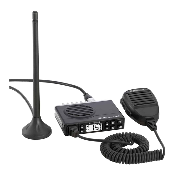
Model MXT100 Installing the Antenna The MXT100 includes a “magnetic mount” antenna, intended to be attached to the vehicle’s roof, trunk or similar location. Specific installation requirements vary between vehicles. Use the following guidelines to install the antenna. *Where you locate your antenna does make a difference.* Some general rules for antenna location that can aid radio performance: 1. -
Page 8: Electrical And Rear Panel Connections
Model MXT100 Electrical and Rear Panel Connections Refer to Rear Panel Connections for rear panel connector locations. NOTE: Radio antenna is installed separately. 1. The power cord supplied with the MXT100 is equipped with a cigarette lighter adapter for easy installation. Simply plug the connector into the vehicle’s cigarette lighter. -
Page 9: Controls And Indicators
Model MXT100 When selecting an external speaker, ensure the speaker has 8-ohm impedance and is rated for 4.0 watts. NOTE: When an external speaker is connected, the radio’s internal speaker is automatically disabled. CONTROLS AND INDICATORS Operating Controls Volume Up – Press to increase radio volume. Channel Up –... -
Page 10: Lcd Display
Model MXT100 LCD Display Receiving Icon – Indicates the radio is receiving transmission from another user. CTCSS / DCS Icon – Indicates a Continuous Tone Coded Squelch System (CTCSS) or Digitally Coded Squelch (DCS) Privacy Code has been enabled for the currently selected channel. Scanning Icon –... -
Page 11: Operating Your Radio
Model MXT100 1. ANT Jack – PL-258 UHF connector for external antenna (included). 2. EXT SPKR Jack – 3.5mm Audio connector for optional external speaker (purchased separately) (see Using an External Speaker for specifications). 3. 13.8V DC Jack – 2-pin DC connector for 12V DC nominal input power connection OPERATING YOUR RADIO About Range... -
Page 12: Power On/Off
Model MXT100 Power On/Off To turn the radio on and off: 1. With the radio off, press and hold the Power On/Off button for two seconds to turn the radio on. The LCD display will show all icons for one second and then display the most recently selected channel. -
Page 13: Utility Functions
Model MXT100 The RX/TX icon will show continuously on the LCD display while transmitting. 3. To receive a call, release the PTT button on the microphone. The RX/TX icon will show on the LCD display when your radio is receiving a transmission. -
Page 14: Adjusting The Display Illumination
Model MXT100 To “lock” and “unlock” the keypad: 1. Be sure the radio is turned on (see Power On/Off). 2. Press and hold the Menu button for two seconds. The Keypad Lock icon will show on the LCD display when the keypad is “locked.”... -
Page 15: Scanning For Active Channels
Model MXT100 4. Press the Volume Up or Volume Down button to increase or decrease radio volume. 5. Once the radio volume has been adjusted to the desired level, press the Monitor/Quiet Channel button to exit Monitor mode. Scanning for Active Channels Your MXT100 includes an “auto-scan”... -
Page 16: Menu" Mode Functions
Model MXT100 3. Press and hold the Scan button. The selected channel is removed from the list of “scanned” channels and will not be included in “auto-scan.” 4. Repeat steps 1 through 3 to return a removed channel to the list of “scanned”... - Page 17 Model MXT100 When a transmission with the correct tone is received, the mute is removed and the voice audio can be heard. When the transmission ends the channel is muted again. Transmissions that do not have the correct tone are not heard. The MXT100 has 142 Privacy Codes (38 CTCSS codes and 104 DCS codes), which can be applied to any channel.
-
Page 18: Adjusting Squelch Sensitivity
Model MXT100 Adjusting Squelch Sensitivity The MXT100 has adjustable squelch sensitivity. The minimum squelch level of 00 is the most sensitive, which allows the squelch to open on very weak signals. Setting the squelch to the maximum setting of 09 requires very strong signals to open the squelch. -
Page 19: Selecting The Transmit (Tx) Power Level
Model MXT100 5. When the desired “beep” tone volume level is shown on the LCD display, press the Menu button (or wait 3 seconds) to confirm your selection. Selecting the Transmit (TX) Power Level The MXT100 provides two transmit power levels; HI and Lo. The Lo power level is generally suitable when operating under optimum conditions (see About Range). -
Page 20: Care And Maintenance
Model MXT100 CARE AND MAINTENANCE CAUTION: DO NOT use alcohol or cleaning solutions to clean the radio. DO NOT immerse the radio in water. 1. Use a soft cloth moistened with water to clean the radio. 2. Dry the radio with a dry lint-free cloth should it get wet. TROUBLESHOOTING GUIDE If you experience difficulties using your MXT100, refer to the following chart to correct common operation problems. -
Page 21: Specifications
Model MXT100 SPECIFICATIONS Channels: 15 GMRS Channels Privacy Codes: 38 CTCSS; 104 DCS Operating Frequency: UHF; 462.5500 ~ 462.725 MHz Power Source: 13.8 VDC Nominal GMRS Frequency Chart Ch. No. Ch. Freq. (MHz) Ch. No. Ch. Freq. (MHz) 462.5625 462.550 462.5875 462.575 462.6125... -
Page 22: Dcs Privacy Codes Chart
Model MXT100 DCS Privacy Codes Chart Code Code Code Code midlandusa.com Page 22... -
Page 23: Limited Warranty (United States And Canada)
Subject to the exclusions set forth below, Midland Radio Corporation will repair or replace, at its option without charge, any Midland FRS/GMRS which fails due to a defect in material or workmanship within One Year following the initial consumer purchase. - Page 24 5900 Parretta Drive Kansas City, MO 64120 Call 816.241.8500 We’d love to hear from you! Let us know what you think of your new Midland product at or by visiting us at www.midlandusa.com Note: Features & Specifications are subject to change without notice.
Need help?
Do you have a question about the Micro Mobile MXT100 and is the answer not in the manual?
Questions and answers