Table of Contents
Advertisement
Quick Links
Advertisement
Table of Contents

Related Manuals for Midland MXT275J


Summary of Contents for Midland MXT275J
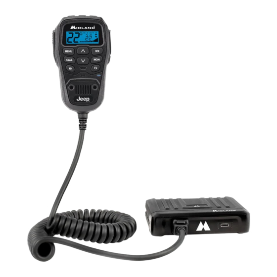
- Page 1 MXT275...
-
Page 2: Table Of Contents
Model MXT275 Table of Contents …………………………………..……. WELCOME TO THE WORLD OF MIDLAND FEATURES………………………………………………………………………………………..3 FCC NOTICE……………………..…………….……………………………………………..…..4 Exposure to Radio Frequency Energy………..……………………………………………..4 INSTALLING YOUR RADIO………………………………………………………………….…...5 Preparation for Installation…..…………………………………………..5 Installing the Mounting Bracket…...…………………………………………..6 Installing the Antenna……………….………………………………………….7 Electrical and Rear Panel Connections..……………………………………..8 Connecting the Microphone…………….……………………………………..8 Using an External Speaker……………….…………………………………...9... -
Page 3: Welcome To The World Of Midland
ACCESSORIES…………..……………………………………………………………………..30 LIMITED WARRANTY…………………………………………………………………………..31 WELCOME TO THE WORLD OF MIDLAND RADIO Congratulations on your purchase of a high quality MIDLAND product. Your MXT275 two-way radio represents state-of-the-art high tech engineering. Designed for General Mobile Radio Service (GMRS) operation, this compact package is big on performance. It is a quality piece of electronic equipment, skillfully constructed with the finest components. -
Page 4: Fcc Notice
This device complies with Part 15 of the FCC rules. Operation is subject to the condition that this device does not cause harmful interference Exposure To Radio Frequency Energy Your Midland radio is designed to comply with the following national and international standards and guidelines regarding exposure of human beings to radio frequency electromagnetic energy. -
Page 5: Installing Your Radio
Model MXT275 INSTALLING YOUR RADIO Preparation for Installation This radio may be installed in any 12-volt, negative ground system vehicle. Most current U.S. and foreign vehicles use a negative ground system, but some older models and some newer large trucks may have a positive ground. -
Page 6: Installing The Mounting Bracket
Model MXT275 Installing the Mounting Bracket 1. Using the mounting bracket as a template, mark the location of each screw hole under the dash. Use a nail or other sharp pointed object to mark the hole locations. 2. Attach the bracket to the dash with the Phillips head sheet metal screws provided. -
Page 7: Installing The Antenna
Model MXT275 Installing the Antenna The MXT275 includes a “magnetic mount” antenna, intended to be attached to the vehicle’s roof, trunk or similar location. Specifi c installation requirements vary between vehicles. Use the following guidelines to install the antenna. *Where you locate your antenna affects performance.* Some general rules for antenna location that can aid radio performance: 1. -
Page 8: Electrical And Rear Panel Connections
Model MXT275 Electrical and Rear Panel Connections Refer to Rear Panel Connections for rear panel connector locations. NOTE: Radio antenna is installed separately. 1. The power cord supplied with the MXT275 is equipped with a cigarette lighter adapter for easy installation. Simply plug the connector into the vehicle’s cigarette lighter. -
Page 9: Controls And Indicators
Model MXT275 Using an External Speaker The MXT275 provides a rear-panel jack for connection of an optional external speaker (purchased separately). When selecting an external speaker, ensure the speaker has 8-ohm impedance and is rated for 4.0 watts. NOTE: When an external speaker is connected, the radio’s internal speaker is automatically disabled. - Page 10 Model MXT275 Lock - Press and hold to lock the keypad 7. Mic - Built-in Microphone 8. WX - Press and release the WX button to enter the Weather Radio Mode 9. MON - Press and release the MON button to activate the Monitor Function Scan - Press and release the Scan Button to activate the Channel Scan Function...
-
Page 11: Front Panel Connections
Model MXT275 Front Panel Connections 1. Microphone Jack 2. USB-C Port Back Panel Connections 1. ANT Jack - SO-239 UHF connector for external antenna (included) 2. EXT SPKR Jack - 3.5mm audio connector for optional external speaker (purchased separately) (see Using an External Speaker for specifications). -
Page 12: Lcd Display
Model MXT275 LCD Display 1. Channel Icon - Shows the selected transmit/receive channel. Receiving Icon - Indicates the radio is receiving a transmission from another user. Repeater Icon - Shows the selected transmit/receive repeater channel. Transmitting Icon - Indicates the radio is transmitting to another user. -
Page 13: Operating Your Radio
Model MXT275 OPERATING YOUR RADIO About Range Your MXT275 is designed to give you maximum operating range under optimal conditions. Maximum Range / No Sight Obstruction Medium Range / Partial Obstruction to Line of Sight Short Range / Major Obstruction to Line of Sight Optimal conditions for maximum operating range are: ▪... -
Page 14: Power On/Off
Model MXT275 Power On/Off To turn the radio on and off: 1. With the radio off, press and hold the Power Button. You will hear a tone when the radio is on. ▪ The LCD display will show all icons for one second and then display the most recently selected channel. -
Page 15: To Transmit And Receive A Call
Model MXT275 Transmitting and Receiving a Call IMPORTANT! To communicate between two radios, both radios must be set to the same channel and Privacy Code (see Selecting a Privacy Code) selections. To transmit and receive a call: Be sure the radio is turned on (see Power On/Off) 2. -
Page 16: Using Monitor Mode
Model MXT275 To “lock” and “unlock” the keypad: 1. Be sure the radio is turned on (see Power On/Off) 2. Press and hold the Lock button for three seconds. ▪ The Keypad Lock icon will show on the LCD display when the keypad is “locked.”... -
Page 17: Scanning For Active Channels
Model MXT275 Scanning for Active Channels Your MXT275 includes an “auto-scan” mode that continuously scans all 15 available channels for activity. To enter and exit “auto-scan” mode: 1. Be sure the radio is turned on (see Power On/Off). 2. Press and release the Scan button to enter “auto-scan” mode. ▪... -
Page 18: To Manually Set The Weather Channel
Model MXT275 2. The radio will then scan all 10 weather channels and will lock on to the strongest weather channel in your area. 3. Use the Channel Up or Channel Down on the microphone to force the radio to re-scan the weather channels while the radio is in scan mode. ▪... -
Page 19: Menu Mode Functions
Model MXT275 MENU MODE FUNCTIONS The “Menu” mode provides access to the features and functions shown in the chart below. For additional utility functions, see UTILITY FUNCTIONS. Standard Channel Menu Quick Reference Chart Repeater Channel Menu Quick Reference Chart Pt - Privacy Tones - Use this option to set the privacy code. tC - Transmit Privacy Tone/Code - Use this option to set the transmitter privacy code on repeater channels. - Page 20 Model MXT275 When a transmission with the correct tone is received, the mute is removed and the voice audio can be heard. When the transmission ends the channel is muted again. Transmissions that do not have the correct tone are not heard. The MXT275 has 142 Privacy Codes (38 CTCSS codes and 104 DCS codes), which can be applied to any channel.
-
Page 21: Selecting The Transmit (Tx) Power Level
Model MXT275 6. When the desired Privacy Code is shown on the LCD display, press the Lock Button to confirm your selection. YOU MUST PRESS THE LOCK BUTTON TO CONFIRM YOUR SELECTION OR THE PRIVACY CODE WILL NOT BE CHANGED. NOTE: If you select a CTCSS Privacy Code, any pre-selected DCS Privacy Code will be cancelled, and vice-versa. -
Page 22: Roger Beep
Model MXT275 To adjust the Squelch Sensitivity: 1. Press the Menu button to place the radio in “Menu” mode. 2. Use the Volume Up or Volume Down button to scroll through the menu options until the LCD display shows Sq. 3. -
Page 23: Call Alert Tone
Model MXT275 Call Alert Tone Your MXT275 has 5 selectable Call Alert Tones. Selecting a Call Alert Tone: 1. Press and release the Menu button to place the radio in “Menu” mode. 2. Use the Volume Up or Volume Down button to scroll through the menu options until the LCD display shows CA. -
Page 24: Repeater Channels
Model MXT275 Repeater Channels Your MXT275 has the ability to access repeater channels. The use of a repeater can significantly increase a radio’s range and coverage area. Prior to using a repeater you must coordinate with the owner of the repeater to gain permission to use the repeater. -
Page 25: Choosing Your Output Speaker
Model MXT275 5.When the desired color has been selected, press the Lock button to confirm your selection. YOU MUST PRESS THE LOCK BUTTON TO CONFIRM YOUR SELECTION OR THE BACKGROUND COLOR WILL NOT BE CHANGED. Choosing your Output Speaker You can choose which speaker you would like to use for your audio. To Change the Primary Speaker used by your radio: 1. -
Page 26: Care And Maintenance
Model MXT275 CARE AND MAINTENANCE CAUTION: DO NOT use alcohol or cleaning solutions to clean the radio. DO NOT immerse the radio in water. 1. Use a soft cloth moistened with water to clean the radio. 2. Dry the radio with a dry lint-free cloth should it get wet. TROUBLESHOOTING GUIDE If you experience difficulties using your MXT275, refer to the following chart to correct common operation problems. -
Page 27: Specifications
Model MXT275 SPECIFICATIONS Channels: 15 GMRS Channels and 10 NOAA Weather Channels Privacy Codes: 38 CTCSS; 104 DCS Operating Frequency: UHF; 462.5500 ~ 462.725 MHz Repeater Frequency: UHF; 467.5500 ~ 467.725 MHz Power Source: 13.8 VDC Nominal GMRS Frequency Chart Ch. -
Page 28: Ctcss Privacy Codes Frequency Chart
Model MXT275 CTCSS Privacy Codes Frequency Chart Code Freq. Code Freq. Code Freq. Code Freq Code Freq 67.0 9 118.8 156.7 210.7 71.9 123.0 162.2 218.1 74.4 97.4 127.3 167.9 225.7 77.0 100.0 131.8 173.8 233.6 79.7 103.5 136.5 179.9 241.8 82.5 107.2... - Page 29 Model MXT275 LIMITED WARRANTY (United States) Subject to the exclusions set forth below, Midland Radio Corporation will repair or replace, at its option without charge, any MXT275 which fails due to a defect in material or workmanship within One Year following the initial consumer purchase.
- Page 30 Kansas City, MO 64120 Call 816.241.8500 We’d love to hear from you! Let us know what you think of your new Midland product at: or by visiting us at: midlandusa.com Note: Features and Specifi cations are subject to change without notice.
Need help?
Do you have a question about the MXT275J and is the answer not in the manual?
Questions and answers