Table of Contents
Advertisement
Advertisement
Table of Contents

Related Manuals for Midland MXT115


Summary of Contents for Midland MXT115
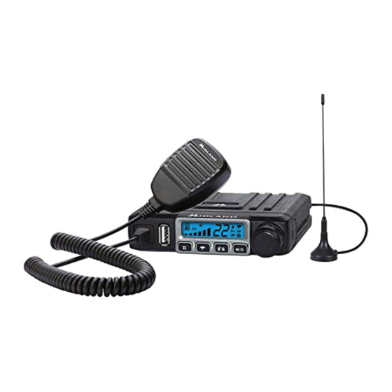
- Page 1 MXT115...
-
Page 2: Table Of Contents
CONTROLS AND INDICATORS..................Operating Controls....................is all solid-state and mounted on a rugged printed circuit board. Your Microphone Controls....................MXT115 radio is designed for reliable and trouble-free performance for Rear Panel Connections..................years to come. LCD Display......................OPERATING YOUR RADIO.................... -
Page 3: Fcc Notice
Exposure To Radio Frequency Energy 5. Determine a mounting location for your radio. The MXT115 is designed to be installed under the dash or vertically on the center console. Choose Your Midland radio is designed to comply with the following national and a location that does not impair visibility or interfere with driving. -
Page 4: Installing The Antenna
Model MXT115 Installing the Mounting Bracket Installing the Antenna The MXT115 includes a “magnetic mount” antenna, intended to be 1. Using the mounting bracket as a attached to the vehicle’s roof, trunk or similar location. Specific installation template, mark the location of each requirements vary between vehicles. -
Page 5: Using An External Speaker
NOTE: Radio antenna is installed separately. When selecting an external speaker, ensure the speaker has 8-ohm 1. The power cord supplied with the MXT115 is equipped with a cigarette impedance and is rated for 4.0 watts. lighter adapter for easy installation. Simply plug the connector into the vehicle’s cigarette lighter. -
Page 6: Lcd Display
Model MXT115 Model MXT115 LCD Display Microphone Controls Transmitting Icon - Indicates the radio is transmitting to another user. Monitor Icon - Indicates when the radio is in monitor mode 3. Channel Icon - Shows the selected transmit/receive channel. Key Lock Icon - Indicates KEY LOCK mode is on 1. -
Page 7: Operating Your Radio
1. With the radio off, turn the knob clockwise. You will hear a tone when the radio is on. Your MXT115 is designed to give you maximum operating range under ▪ The LCD display will show all icons for one second and then display optimum conditions. -
Page 8: Locking The Keypad
2. Be sure you have selected the desired channel (see Selecting the Utility functions let you configure several operational parameters of the Active Channel) MXT115 to suit your personal preferences. For additional functions, see “MENU” MODE FUNCTIONS. 3. Press and hold the Monitor/Scan button to enter Monitor mode. - Page 9 2. Use the Channel Up or Channel Down on the microphone to select the desired Weather Channel Your MXT115 has a NOAA Weather Radio function, to enable the user to 3. Press and hold the Weather button to turn the Weather Alert on. ▪...
-
Page 10: Features
For additional utility functions, see UTILITY FUNCTIONS. MXT115 “Menu” Mode Quick Reference Chart The MXT115 has 142 Privacy Codes (38 CTCSS codes and 104 DCS codes), which can be applied to any channel. If desired, you can select a different Privacy Code for each channel. -
Page 11: Lcd Display
Selecting the Transmit (TX) Power Level ▪ The default squelch setting is 04, which generally provides reliable The MXT115 provides two transmit power levels; HI and Lo. the Lo power squelch operation for most applications. level is generally suitable when operating under optimum conditions (see About Range). -
Page 12: Call Alert Tone
Model MXT115 Repeater Channels Call Alert Tone Your MXT115 has the ability to access repeater channels. The use of a re- Your MXT115 has 5 selectable Call Alert Tones peater can significantly increase a radio’s range and coverage area. Prior... -
Page 13: About Range
2. Dry the radio with a dry lint-free cloth should it get wet. TROUBLESHOOTING GUIDE You can restore the original (factory default) settings for your MXT115 at any time. If you experience difficulties using your MXT115, refer to the following chart to correct common operation problems. -
Page 14: Repeater Channels
Model MXT115 Model MXT115 SPECIFICATIONS Channels: 15 GMRS Channels and CTCSS Privacy Codes Frequency Chart 10 NOAA Weather Channels Code Freq. Code Freq. Code Freq. Code Freq Code Freq Privacy Codes: 38 CTCSS; 104 DCS 67.0 9 118.8 156.7 210.7 71.9... - Page 15 Model MXT115 Model MXT115 ACCESSORIES Accessories can be purchased at midlandusa.com 2-Way Radios Weather Radios HD Wearable Video Cameras 2-Way Radios Emergency Crank Radios CB Radios Page 28 midlandusa.com Page 29 midlandusa.com...
- Page 16 Subject to the exclusions set forth below, Midland Radio Corporation will repair or replace, at its option without charge, any Midland FRS/GMRS which fails due to a defect in material or workmanship within One Year following the initial consumer purchase.
-
Page 17: Specifications
5900 Parretta Drive Kansas City, MO 64120 Call 816.241.8500 We’d love to hear from you! Let us know what you think of your new Midland product at: or by visiting us at: midlandusa.com Note: Features and Specifications are subject to change without notice.
Need help?
Do you have a question about the MXT115 and is the answer not in the manual?
Questions and answers