Table of Contents
Advertisement
Quick Links
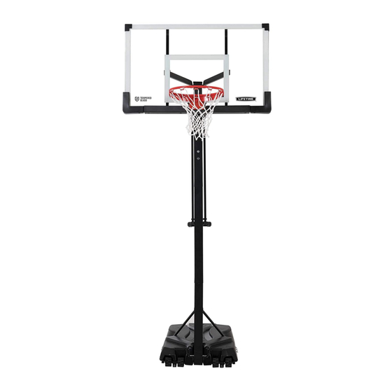
POWER LIFT
BASKETBALL SYSTEM
MODEL 90600
BEFORE ASSEMBLY:
• Decide with what to fi ll the base
(sand is recommended)
• At least 2 adults recommended for setup
WATCH
3D ANIMATION
OF THE FULL ASSEMBLY
SCAN THE
CODE
IMPORTANT, RETAIN FOR FUTURE REFERENCE: READ CAREFULLY
Save this instruction in the event that the manufacturer must be contacted for replacement parts.
TOOLS REQUIRED
1/2", 9/16", 3/4"
(x2)
(x1)
(x1)
(x1)
QUESTIONS?
CONTACT LIFETIME
Dial 1-800-225-3865
7:00 am-5:00 pm (M-F) MST
and 9:00 am-1:00 pm (Sat) MST
(English, Français, Español)
®
OR SEARCH
1215666
11/16"
(x1)
3/16"
(x2, included)
(375 lb)
®
CUSTOMER SERVICE:
Live Chat:
www.lifetime.com/customerservice
(click on "Live Chat" tab)
ASSEMBLY INSTRUCTIONS
1/2", 3/4"
(x1)
(x1)
(x1)
(x1)
(x1)
(x1)
For Customer Service in Mainland
Europe and the United Kingdom,
E-mail: cs@lifetimeproducts.eu
TABLE OF CONTENTS
Icon Legend................................2
Warnings & Notices....................3
Pole Assembly............................4
Pole-to-Base Assembly................8
Backboard-to-Rim Assembly......12
Backboard-to-Pole Assembly.....17
Handle Assembly......................24
Final Assembly.........................29
Maintenance.........................33
Registration........................33
Warning Sticker........................34
Warranty................................35
Model Number: 90600
Product ID:
Advertisement
Table of Contents

Related Manuals for Lifetime POWER LIFT 90600


Summary of Contents for Lifetime POWER LIFT 90600
-
Page 1: Table Of Contents
(x1) Warranty........35 (x1) (375 lb) (x1) (x1) Model Number: 90600 ® QUESTIONS? CONTACT LIFETIME CUSTOMER SERVICE: Product ID: Dial 1-800-225-3865 Live Chat: For Customer Service in Mainland www.lifetime.com/customerservice Europe and the United Kingdom, 7:00 am–5:00 pm (M–F) MST E-mail: cs@lifetimeproducts.eu (click on “Live Chat”... -
Page 2: Icon Legend
ICON LEGEND • Indicates special heed should be taken when reading. • Indicates the parts to be used for a section. • Indicates no parts required for a specifi c section. • Indicates the hardware to be used for a section. •... -
Page 3: Warnings & Notices
WARNINGS & NOTICES SAFETY INSTRUCTIONS FAILURE TO FOLLOW THESE WARNINGS MAY RESULT IN SERIOUS INJURY OR PROPERTY DAMAGE AND WILL VOID WARRANTY. Owner must ensure that all players know and follow these rules for safe operation of the system. To ensure safety, do not attempt to assemble this product without following the instructions carefully. Check entire box and inside all packing material for parts and/or additional instruction material. -
Page 4: Pole Assembly
POLE ASSEMBLY HARDWARE REQUIRED Hardware Bag ABE (x2) CIH (x2) AAF (x2) ADS (x2) ABZ (x2) ABR (x2) ABB (x2) PARTS REQUIRED Metal Parts 43 3/8” (110 cm) ALH (x1) ALL (x1) Warning Sticker 43 3/8” (110 cm) ALF (x1) 27 5/8”... - Page 5 SECTION 1 (CONTINUED) TOOLS AND HARDWARE REQUIRED 9/16" (≈14 mm) ABE (x2) ABB (x2) (x2) ABR (x2) AAF (x2) • Insert the Hex Bolts (ABE) with the Washers (AAF) into the • Secure the Pole Bracket (ALL) to the Top Pole with Top Pole (ALH) as shown.
- Page 6 SECTION 1 (CONTINUED) TOOLS AND HARDWARE REQUIRED ADS (x2) (x1) CIH (x2) • Align the hole in the bottom of the Top Pole (ALH) • Secure the Middle Pole to the Bottom Pole (ALE) using with the slot in the top of the Middle Pole (ALF). Insert the same method as step 1.3.
- Page 7 SECTION 1 (CONTINUED) TOOLS AND HARDWARE REQUIRED ABZ (x2) (x1) (x1) • Strike the end of the Pole Assembly on a piece of scrap wood or • Flip the Pole over and repeat cardboard 5–6 times. step 1.5 for the opposite end of the Pole Assembly.
-
Page 8: Pole-To-Base Assembly
POLE-TO-BASE ASSEMBLY HARDWARE REQUIRED Hardware Bag DRZ (x1) BTS (x1) CCL (x2) AAE (x2) ABD (x4) AAO (x2) PARTS REQUIRED Metal Parts ” 38" (≈96,5 cm) AJD (x1) ALI (x2) Plastic Parts AMU (x2) AJN (x1) AJM (x1) TOOLS REQUIRED CCL-3/16"... - Page 9 SECTION 2 (CONTINUED) TOOLS AND HARDWARE REQUIRED (x1) • Screw the Base Cap (AJN) onto the Base (AJM) as shown. Rubber Gasket • Make sure the Rubber Gasket is inside the Base Cap. • Slide the Axle (AJD) through one of the Wheels (AMU) and into the Base (AJM) as shown. Then have one adult position the Bottom Pole (ALE) within the Base as shown with the lip at the bottom of the pole facing outward.
- Page 10 SECTION 2 (CONTINUED) TOOLS AND HARDWARE REQUIRED 1/2" (13 mm) (x2) AAE (x2) AAO (x2) ABD (x4) • Attach the fl attened end of the Pole Brace (ALI) to the Base (AJM) with the hardware shown. Only fi nger tighten the hardware.
- Page 11 SECTION 2 (CONTINUED) TOOLS AND HARDWARE REQUIRED 3/16" (5 mm) CCL (x2) 1/2" (13 mm) DRZ (x1) BTS (x1) (x2) • Attach the Pole Braces (ALI) to the Bottom Pole (ALE) with the hardware shown. • Tip the system forward and rest the Pole on the ground. Do not stand the system up until it is fi lled with either sand or water later in the assembly.
-
Page 12: Backboard-To-Rim Assembly
BACKBOARD-TO-RIM ASSEMBLY HARDWARE REQUIRED Hardware Bag EAP (x2) AAQ (x2) AAV (x2) ADR (x4) ABK (x4) APZ (x1) APY (x1) AOW (x1) AJW (x2) ABQ (x1) PARTS REQUIRED Metal Parts Plastic Parts BGR (x1) AJI (x1) ALX (x1) AMA (x1) ALD (x1) TOOLS REQUIRED 1/2”... - Page 13 SECTION 3 (CONTINUED) TOOLS AND HARDWARE REQUIRED 1/2” (13 mm) APY (x1) (x1) ABQ (x1) (Not to scale) EAP (x2) (Not to scale) AAQ (x1) • Insert two Carriage Bolts (EAP) through the Rim Pivot Bracket (APY) as shown. •...
- Page 14 SECTION 3 (CONTINUED) TOOLS AND HARDWARE REQUIRED 1/2” (13 mm) (x2) 1/2” (13 mm) AAQ (x1) ABK (x2) (x1) • Slide the end of the Axle (ABQ) through the Rim (ALX) and the Rim Pivot Bracket (APY). Press the Push Nut (AAQ) onto the end of the Axle.
- Page 15 SECTION 3 (CONTINUED) TOOLS AND HARDWARE REQUIRED APZ (x1) 1/2” (13 mm) (x2) AAV (x2) (Not to scale) • Insert the U-Bolt (APZ) through the U-Bolt Washer Plate (BGR) and into the back of the Backboard as shown. • Thread the Jam Nuts (AAV) all the way down on the U-Bolt as shown.
- Page 16 SECTION 3 (CONTINUED) TOOLS AND HARDWARE REQUIRED AOW (x1) AJW (x2) 1/2” (13 mm) (x2) (Not to scale) (Not to scale) ADR (x4) ABK (x2) (x1) • Slide the Compression Springs (AJW) onto the U-Bolt, and place the Spring Retainer Plate (AOW) over the Compression Springs.
-
Page 17: Backboard-To-Pole Assembly
BACKBOARD-TO-POLE ASSEMBLY HARDWARE REQUIRED Hardware Bag 7 1/16" (≈18 cm) (Not actual length) AAX (x4) AAD (x1) AOR (x6) 5” AQB (x2) (Not actual length) AAN (x2) AQD (x1) ABP (x6) ANK (x4) AQC (x2) ANU (x2) ANS (x8) ANQ (x2) ANP (x1) PARTS REQUIRED Plastic Part... - Page 18 SECTION 4 (CONTINUED) TOOLS AND HARDWARE REQUIRED 1/2” (≈13 mm) 1/2” (≈13 mm) AQB (x2) AAN (x2) • Insert one end of the Tie Plate (BLC) into the slot • Insert the opposite end of the Tie Plate into the slot on the Lower Extension Arm (BGP) as shown.
-
Page 19: Parts Identifier
PARTS IDENTIFIER This page intentionally left blank... - Page 20 PARTS IDENTIFIER Metal Parts 43 3/8” (110 cm) ALH (x1) ALX (x1) Warning Sticker 43 3/8” (110 cm) ALF (x1) 27 5/8” (70.2 cm) 27 5/8 in/po (70,2 cm) ALE (x1) • The Bottom Pole (ALE) has ” been designed with an indent AJD (x1) AMA (x1) at one end.
- Page 21 PARTS IDENTIFIER Plastic Parts AJI (x1) AMU (x2) AJM (x1) AKF (x1) AJN (x1) ALM (x1) AKG (x1) ALD (x1) AMN (x1) AKI (x1) AJQ (x1) AKZ (x1) BAB (x1) BAA (x2) AKP (x1) HARDWARE REQUIRED...
- Page 22 PARTS IDENTIFIER This page intentionally left blank...
- Page 23 SECTION 4 (CONTINUED) TOOLS AND HARDWARE REQUIRED 7 1/16" (≈18 cm) 3/4” (≈19 mm) AAD (x1) (x2) (Not actual length) AAX (x1) AOR (x2) ABP (x2) AQC (x2) • Insert the Extension Arm Caps (AQC) into the ends of the Lower Extension Arms as shown. •...
-
Page 24: Handle Assembly
SECTION 4 (CONTINUED) TOOLS AND HARDWARE REQUIRED 3/4” (≈19 mm) 5” 3/4” (≈19 mm) (Not actual length) AQD (x1) ABP (x2) ANK (x2) AAX (x1) • Attach the Upper Extension Arms (BGO) to the Top Pole (ALH) with the hardware shown. If necessary, use a Rubber Mallet to tap the bolt into place. - Page 25 SECTION 4 (CONTINUED) TOOLS AND HARDWARE REQUIRED 11/16” (≈18 mm) ANQ (x2) (x2) 3/4” (≈19 mm) (x2) ANP (x1) ABP (x2) AOR (x2) CAUTION: HAVE ONE ADULT HOLD THE BACKBOARD IN PLACE UNTIL ASSEMBLY HAS BEEN COMPLETED! • Lay the Backboard and Rim assembly next to the Pole assembly. Rest the Rim on cardboard to prevent scratching.
- Page 26 SECTION 4 (CONTINUED) TOOLS AND HARDWARE REQUIRED 3/4” (≈19 mm) (x2) ANU (x2) ANK (x2) AAX (x2) AOR (x2) • Attach the Upper Extension Arms (BGO) to the Backboard (AJI) with the hardware shown. • Tighten the Centerlock Nut (AAX) until it is fl...
- Page 27 SECTION 4 (CONTINUED) TOOLS AND HARDWARE REQUIRED ANS (x8) • Insert Nylon Plugs (ANS) into the locations indicated on the back of the Backboard. 4.10 • Insert the Pole Cap (ALM) into the end of the Top Pole.
- Page 28 HANDLE ASSEMBLY HARDWARE REQUIRED Hardware Bag AQE (x1) BSG (x1) ABM (x2) ABB (x2) AAX (x2) 6 1/2" (≈16.5 cm) 7 1/16" (≈18 cm) AAW (x1) AAD (x1) 6 1/2" (≈16.5 cm) AOR (x2) AKH (x1) ABA (x2) ACX (x1) APR (x1) PARTS REQUIRED Metal Part...
-
Page 29: Final Assembly
SECTION 5 (CONTINUED) TOOLS AND HARDWARE REQUIRED 1/2” (13 mm) (x2) ACX (x1) BSG (x1) • Slide the Gas Spring Cover (AKG) onto • Align the holes in the Gas Spring Cover (AKG) and the Gas Spring (AKF) the Gas Spring (AKF) as shown. with the holes in the Pole Bracket (ALL), and attach the Gas Spring assembly to the Pole Bracket with the hardware shown. - Page 30 SECTION 5 (CONTINUED) TOOLS AND HARDWARE REQUIRED 9/16” (≈14 mm) 6 1/2" (≈16.5 cm) (x2) ABA (x1) ABB (x1) • Position the Trigger (AMN) inside of the Handle (AKI) as shown, and secure the Trigger to the Handle with the hardware shown.
- Page 31 SECTION 5 (CONTINUED) TOOLS AND HARDWARE REQUIRED 6 1/2" (≈16.5 cm) 3/4” (≈19 mm) (x2) 9/16” (≈14 mm) AAW (x1) 6 1/2" (≈16.5 cm) (x2) AAX (x1) ABM (x2) ABB (x1) ABA (x1) • Slide the Handle (AKI) under the Gas Spring (AKF) so that the Release Pin (ALV) rests in the channels of the Trigger (AMN). Position the Rear Lifter Arms (ALS) between the Handle and Trigger, and secure with the hardware shown.
- Page 32 SECTION 5 (CONTINUED) TOOLS AND HARDWARE REQUIRED 7 1/16" (≈18 cm) 3/4” (≈19 mm) AKH (x1) (x2) AAD (x1) AAX (x1) APR (x1) • Connect the Rear Lifter Arms (ALS) to the inside of the Lower Extension Arms (BGP) with the hardware shown. Place a Spacer (APR) between the Rear Lifter Arms as shown.
-
Page 33: Maintenance
FINAL ASSEMBLY HARDWARE REQUIRED Hardware Bag ADP (x10) PARTS REQUIRED Plastic Parts AJQ (x1) AKZ (x1) BAB (x1) BAA (x2) AKP (x1) TOOLS REQUIRED (x1) 375 lb (170kg) (x1) (x1) (x1) -
Page 34: Warning Sticker
SECTION 6 (CONTINUED) TOOLS AND HARDWARE REQUIRED (x1) ADP (x10) • Remove the plastic fi lm from the Backboard (AJI), and attach the Center Frame Pad (AJQ) to the Backboard in the location shown with the hardware indicated. Make sure that the Center Frame Pad is oriented and centered on the metal piece of the Backboard. -
Page 35: Warranty
SECTION 6 (CONTINUED) TOOLS AND HARDWARE REQUIRED (375 lb) (x1) (x1) 6.3A Two adults are required to complete assembly. To prevent serious injuries, the Pole should be held down by one adult at all times while the Base is being fi lled. •... - Page 36 SECTION 6 (CONTINUED) TOOLS AND HARDWARE REQUIRED (x1) • Attach the Net (ALX). • If a replacement Net is needed, please call our Customer Service Department. Our Nets are shorter than average to reduce the risk of entanglement. • Raise the Backboard until the top of the Rim measures 10 feet from the playing surface.
- Page 37 ® ® personal data to other third parties, or allow them to use your personal data for their own purposes. We invite you to read our privacy policy at www.lifetime.com REGISTER today! ENREGISTRER CE PRODUIT EN LIGNE À WWW.LIFETIME.COM...
- Page 38 N’accrochez rien au manche, à l’anneau, elevación, ya que esto puede dañar el sistema y anular la garantía. au panneau ni aux leviers sous peine d’endommager l’équipement et d’annuler la garantie. Lifetime Products, Inc., Clearfield, UT 84016 www.lifetime.com # 1180194 1-800-225-3865...
- Page 39 2. This warranty is nontransferable and is expressly limited to the repair or replacement of defective product. If the product is defective within the terms of this warranty, Lifetime Products, Inc. will repair or replace defective parts at no cost to the purchaser.
- Page 40 ® ENHANCE YOUR LIFETIME PURCHASE BY ADDING ACCESSORIES OR OTHER GREAT PRODUCTS To purchase accessories or other Lifetime products, visit us at: ® www.lifetime.com Or call: 1-800-424-3865 7:00 am–5:00 pm (M–F) MST and 9:00 am–1:00 pm Saturday MST www.lifetime.com © 2021...
Need help?
Do you have a question about the POWER LIFT 90600 and is the answer not in the manual?
Questions and answers