Table of Contents
Advertisement
Quick Links
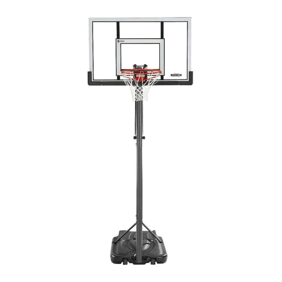
POWER LIFT
BASKETBALL SYSTEM
MODEL #60091
MODEL 90675
BEFORE ASSEMBLY:
• Decide how you would like to fi ll your base
(sand is recommended).
• 2+ people recommended for setup.
Save this instruction in the event that the manufacturer has
to be contacted for replacement parts.
TOOLS REQUIRED
1/2" (13 mm), 7/16" (11 mm), 9/16"
(14 mm), 3/4" (19 mm)
(x2 )
(x1)
(x1)
CONTACT LIFETIME
QUESTIONS?
Call: 1-800-225-3865
7:00 am-5:00 pm (Monday-Friday) MST
and 9:00 am-1:00 pm Saturday MST
®
3/16"(5 mm)
(x2, included)
(x1)
(375 lb)/(170 kg)
®
CUSTOMER SERVICE:
Live Chat: www.lifetime.com
(click on "Ask An Expert" tab)
Video Instructions:
www.youtube.com/lifetimeproducts
ASSEMBLY INSTRUCTIONS
(x1)
(x1)
(x1)
(x1)
(x1)
For Customer Service in Mainland
Europe and the United Kingdom,
E-mail: cs@lifetimeproducts.eu
TABLE OF CONTENTS
Icon Legend................................2
Notices....................................3
Pole Assembly............................4
Pole to Base Assembly...............8
Backboard to Rim Assembly.......12
Backboard to Pole Assembly.......15
Handle Assembly......................20
Final Assembly..........................25
Maintenance Instructions..........29
Registration........................29
Warning Sticker........................30
Warranty................................31
MODEL# AND PRODUCT ID
(you will need both when contacting us)
Model Number: 90675
Product ID:
Advertisement
Table of Contents

Subscribe to Our Youtube Channel
Related Manuals for Lifetime POWER LIFT 90675


Summary of Contents for Lifetime POWER LIFT 90675
-
Page 1: Table Of Contents
CUSTOMER SERVICE: QUESTIONS? (you will need both when contacting us) Model Number: 90675 Call: 1-800-225-3865 Live Chat: www.lifetime.com For Customer Service in Mainland Product ID: Europe and the United Kingdom, (click on “Ask An Expert” tab) 7:00 am–5:00 pm (Monday–Friday) MST E-mail: cs@lifetimeproducts.eu... -
Page 2: Icon Legend
This hardware was designed with this feature in order to prevent loosening later. CONTACT US • Save this instruction in the event that the manufacturer has to be contacted for replacement parts. Call: 1-800-225-3865 7:00 am–5:00 pm (Monday–Friday) MST and 9:00 am–1:00 pm Saturday MST www.lifetime.com/instructions 1182180 3/01/2017... -
Page 3: Notices
WARNINGS & NOTICES / AVERTISSEMENTS ET AVIS / ADVERTENCIAS Y AVISOS SAFETY INSTRUCTIONS FAILURE TO FOLLOW THESE WARNINGS MAY RESULT IN SERIOUS INJURY OR PROPERTY DAMAGE AND WILL VOID WARRANTY. Owner must ensure that all players know and follow these rules for safe operation of the system. To ensure safety, do not attempt to assemble this product without following the instructions carefully. -
Page 4: Pole Assembly
POLE ASSEMBLY HARDWARE REQUIRED Hardware Bag ABE (x2) CIH (x2) AAF (x2) ADS (x2) ABZ (x2) ABR (x2) ABB (x2) PARTS REQUIRED Metal Parts ALH (x1) ALL (x1) Warning Sticker ALF (x1) ALE (x1) TOOLS REQUIRED 9/16” (14 mm) (x1) (x2) (x1) (x1) - Page 5 SECTION 1 (CONTINUED) TOOLS AND HARDWARE REQUIRED 9/16" (14 mm) ABE (x2) ABB (x2) (x2) ABR (x2) AAF (x2) • Insert the Hex Bolts (ABE) with the Washers (AAF) into the • Secure the Pole Bracket (ALL) to the Top Pole with Top Pole (ALH) as shown.
- Page 6 SECTION 1 (CONTINUED) TOOLS AND HARDWARE REQUIRED ADS (x2) (x1) CIH (x2) • Align the hole in the bottom of the Top Pole (ALH) • Secure the Middle Pole to the Bottom Pole (ALE) using with the slot in the top of the Middle Pole (ALF). Insert the same method as step 1.3.
- Page 7 SECTION 1 (CONTINUED) TOOLS AND HARDWARE REQUIRED ABZ (x2) (x1) (x1) • Strike the end of the Pole Assembly on a piece of scrap wood or • Flip the Pole over and repeat cardboard 5–6 times. step 1.5 for the opposite end of the Pole Assembly.
-
Page 8: Pole To Base Assembly
POLE TO BASE ASSEMBLY HARDWARE REQUIRED Hardware Bag DRZ (x1) BTS (x1) CCL (x2) AAE (x2) ABD (x4) AAO (x2) PARTS REQUIRED Metal Part ” 38” AJD (x1) ALI (x2) 1/2” x 21 3/4” Plastic Parts AMU (x2) AJN (x1) AJM (x1) TOOLS REQUIRED CCL-3/16”... - Page 9 SECTION 2 (CONTINUED) TOOLS AND HARDWARE REQUIRED • Screw the Base Cap (AJN) onto the Base (AJM) as shown. Rubber Gasket • Make sure the Rubber Gasket is inside the Base Cap. • Slide the 1/2” x 21 3/4” Axle (AJD) through one of the Wheels (AMU) and into the Base (AJM) as shown. Then have one adult position the Bottom Pole (ALE) within the Base as shown with the lip at the bottom of the pole facing outward.
- Page 10 SECTION 2 (CONTINUED) TOOLS AND HARDWARE REQUIRED 1/2" (x2) AAE (x2) AAO (x2) ABD (x4) • Attach the fl attened end of the Pole Brace (ALI) to the Base (AJM) with the hardware shown. Only fi nger tighten the hardware. •...
- Page 11 SECTION 2 (CONTINUED) TOOLS AND HARDWARE REQUIRED 3/16” CCL (x2) 1/2" (x2) DRZ (x1) BTS (x1) • Attach the Pole Braces (ALI) to the Bottom Pole (ALE) with the hardware shown. • Tip the system forward and rest the Pole on the ground. Do not stand the system up until it is fi lled with either sand or water later in the assembly.
-
Page 12: Backboard To Rim Assembly
BACKBOARD TO RIM ASSEMBLY HARDWARE REQUIRED Hardware Bag AAM (x2) DFE (x4) AAV (x2) ABB (x4) AAJ (x2) ABD (x2) ABK (x4) ABF (x2) APZ (x1) AOW (x1) AJW (x2) PARTS REQUIRED Metal Parts Plastic Parts AJI (x1) ALX (x1) DFD (x1) ALD (x1) AMY (x2) - Page 13 SECTION 3 (CONTINUED) TOOLS AND HARDWARE REQUIRED 1/2”(x2) AAM (x2) ABK (x2) ABF (x2) APZ (x1) ABD (x2) AAJ (x2) • Insert two 5/16” x 1 1/2” Tap Bolts (AAM) with the 5/16” Washers (ABD) and the 7/16” Rubber Washers (ABF) through the bottom holes in the back of the Rim (ALX) as shown, and secure the hardware with two 5/16”...
- Page 14 SECTION 3 (CONTINUED) TOOLS AND HARDWARE REQUIRED 1/2”(x2) AOW (x1) AJW (x2) 7/16”(x2) AAV (x2) ABK (x2) 9/16”(x2) DFE (x4) ABB (x4) • Turn the Backboard Assemly over. Thread the 5/16” Jam Nuts (AAV) onto each end of the U-Bolt (APZ) as far as they will go.
-
Page 15: Backboard To Pole Assembly
BACKBOARD TO POLE ASSEMBLY HARDWARE REQUIRED Hardware Bag 7 1/16” 7 1/2” (Not actual length) (Not actual length) AAD (x2) DFB (x2) DGA (x2) AAX (x4) ABN (x8) PARTS REQUIRED Metal Part Plastic Parts ” AKC (x2) ALM (x1) ” AKB (x2) TOOLS REQUIRED 3/4”... - Page 16 SECTION 4 (CONTINUED) TOOLS AND HARDWARE REQUIRED 7 1/2” 3/4”(x2) DFB (x1) ABN (x2) AAX (x1) DGA (x1) • Secure the Short Extension Arms (AKC) to the Backboard Brackets in the location shown with the hardware indicated. • A Centerlock Nut will require some effort to thread onto a Bolt.
- Page 17 PARTS IDENTIFIER / IDENTIFICADOR DE PIEZAS / IDENTIFICATEUR DE PIÈCES This page intentionally left blank...
-
Page 18: Parts Identifier
PARTS IDENTIFIER Metal Parts ALH (x1) ALX (x1) Warning Sticker ALF (x1) ALE (x1) ” ” AKB (x2) AKC (x2) ” 38” AJD (x1) ALI (x2) 31” (78.7 cm) ALS (x2) DFD (x1) ALL (x1) AMY (x2) - Page 19 PARTS IDENTIFIER Plastic Parts AJI (x1) AMU (x2) AJM (x1) AJN (x1) ALM (x1) ALD (x1) AKZ (x1) AMN (x1) AKI (x1) AKF (x1) AKP (x1) AKG (x1) BAA (x1) BAB (x1) AJQ (x1) HARDWARE REQUIRED...
-
Page 20: Handle Assembly
PARTS IDENTIFIER This page intentionally left blank... - Page 21 SECTION 4 (CONTINUED) SECTION 4 (CONTINUED) TOOLS AND HARDWARE REQUIRED TOOLS AND HARDWARE REQUIRED 7 1/2” 3/4”(x2) ABN (x2) DFB (x1) AAX (x1) DGA (x1) • Secure the ends of the Long Extension Arms (AKB) that only have one hole to the Backboard Brackets in the location shown with the hardware indicated.
- Page 22 SECTION 4 (CONTINUED) SECTION 4 (CONTINUED) TOOLS AND HARDWARE REQUIRED TOOLS AND HARDWARE REQUIRED 7 1/16” 3/4”(x2) AAD (x2) AAX (x2) ABN (x4) CAUTION: HAVE ONE ADULT HOLD THE BACKBOARD IN PLACE UNTIL ASSEMBLY HAS BEEN COMPLETED! • Lay the Backboard and Rim assembly next to the Pole assembly. Rest the Rim on cardboard to prevent scratching. Then secure the Long Extension Arms (AKB) to the Top Pole (ALH) with the hardware shown.
- Page 23 SECTION 4 (CONTINUED) TOOLS AND HARDWARE REQUIRED • Secure the Short Extension Arms (AKC) to the Top Pole (ALH) with the hardware shown.
- Page 24 HANDLE ASSEMBLY HARDWARE REQUIRED Hardware Bag AQE (x1) BSG (x1) ABB (x2) ABM (x2) (16.5 cm) 1/2” 1/16”(18 cm) AAX (x2) AAW (x1) AAD (x1) (16.5 cm) 6 1/2 ” ACX (x1) ABA (x2) AAO (x1)* ABT (x1) *Note: Nut AAO will not be used in this assembly.
-
Page 25: Final Assembly
SECTION 5 (CONTINUED) TOOLS AND HARDWARE REQUIRED 1/2” ACX (x1) BSG (x1) • Slide the Gas Spring Cover (AKG) onto the Gas Spring (AKF) as shown. • Align the holes in the Gas Spring Cover and the Gas Spring with the holes in the Pole Bracket (ALL), and attach the Gas Spring assembly to the Pole Bracket with the hardware shown. - Page 26 SECTION 5 (CONTINUED) TOOLS AND HARDWARE REQUIRED (16.5 cm) 6 1/2 ” 9/16” (x2) ABA (x1) ABB (x1) • Position the Trigger (AMN) inside of the Handle (AKI) as shown, and secure the Trigger to the Handle with the hardware shown. •...
- Page 27 SECTION 5 (CONTINUED) TOOLS AND HARDWARE REQUIRED (16.5 cm) 1/2” 3/4” (x2) AAW (x1) (16.5 cm) 6 1/2 ” 9/16” (x2) AAX (x1) ABM (x2) ABB (x1) ABA (x1) • Slide the Handle (AKI) under the Gas Spring (AKF) so that the Release Pin (ALV) rests in the channels of the Trigger (AMN). Position the Rear Lifter Arms (ALS) between the Handle and Trigger, and secure with the hardware shown.
- Page 28 SECTION 5 (CONTINUED) TOOLS AND HARDWARE REQUIRED 1/16”(18 cm) AAD (x1) 3/4” (x2) AAX (x1) ABT (x1) • Connect the Rear Lifter Arms (ALS) to the inside of the Lower Extension Arms (BGP) with the hardware shown. Place a Spacer (ABT) between the Rear Lifter Arms as shown. •...
-
Page 29: Maintenance Instructions
FINAL ASSEMBLY HARDWARE REQUIRED Hardware Bag ADP (x10) PARTS REQUIRED Plastic Parts AKP (x1) BAA (x1) BAB (x1) AJQ (x1) AKZ (x1) TOOLS REQUIRED (375lb)/(170kg) -
Page 30: Warning Sticker
SECTION 6 (CONTINUED) TOOLS AND HARDWARE REQUIRED ADP (x10) • Remove the plastic fi lm from the Backboard (AJI), and attach the Center Frame Pad (AJQ) to the Backboard in the location shown with the hardware indicated. Make sure that the Center Frame Pad is centered on the metal piece of the Backboard as shown. -
Page 31: Warranty
SECTION 6 (CONTINUED) TOOLS AND HARDWARE REQUIRED (375 lb) 6.3A Two adults are required to complete assembly. To prevent serious injuries, the Pole should be held down by one adult at all times while the Base is being fi lled. OPTION A: FILLING WITH SAND (375 lb of sand required) a. - Page 32 SECTION 6 (CONTINUED) TOOLS AND HARDWARE REQUIRED • Attach the Net (AKZ) to the Rim (ALX). • Raise the Backboard until it would not go futher. Use a pencil to mark where the bottom of the Gas Spring Cover (AKG) meets the Gas Spring (AJR).
- Page 33 . And you can rest assured that Lifetime will not sell or provide your personal data to other third parties, or allow them to use your personal data for their own purposes. We invite you to read our privacy policy at www.lifetime.com REGISTER today!
- Page 34 fils électriques. mécanisme a été conçu uniquement pour soutenir le poids du panneau et de sous peine d’endommager l’équipement et d’annuler la garantie. www.lifetime.com #FS16400 10/12/2004...
- Page 35 2. This warranty is nontransferable and is expressly limited to the repair or replacement of defective product. If the product is defective within the terms of this warranty, Lifetime Products, Inc. will repair or replace defective parts at no cost to the purchaser.
- Page 36 ® ENHANCE YOUR LIFETIME PURCHASE BY ADDING ACCESSORIES OR OTHER GREAT PRODUCTS ® To purchase accessories or other Lifetime products, visit us at: www.lifetime.com Or call: 1-800-424-3865...
Need help?
Do you have a question about the POWER LIFT 90675 and is the answer not in the manual?
Questions and answers