
Related Manuals for Texas Instruments TAS3208EVM-LC


Summary of Contents for Texas Instruments TAS3208EVM-LC
- Page 1 TAS3208EVM-LC Low-Cost (LC) Evaluation Module (EVM) for TAS3208 Digital Audio Processor User's Guide Literature Number: SLEU097 April 2008...
- Page 2 SLEU097 – April 2008 Submit Documentation Feedback...
-
Page 3: Table Of Contents
Contents ..........................Preface ........................Overview ....................TAS3208EVM-LC Features ..................TAS3208EVM-LC Block Diagram ................TAS3208EVM-LC PCB Component Mapping ....................Quick Setup Guide ......................Unpacking the EVM ....................... Power Supply Setup ..................PurePath GDE Software Installation ................Developing the Process Flow on the EVM ..................... - Page 4 www.ti.com List of Figures ........................ Block Diagram ....................... Component Mapping ....................Printed Circuit Assembly ................PurePath Studio I C Command File Window List of Tables ....................Related TI Documentation ..................Digital Audio Input Interface (J1) ..................Digital Audio Output Interface (J3) ....................
-
Page 5: Preface
Related Documentation From Texas Instruments Table 1 contains a list of data manuals that have detailed descriptions of the integrated circuits used in the design of the TAS3208EVM-LC. The data manuals can be obtained at www.ti.com. Table 1. Related TI Documentation DEVICE... - Page 6 Before starting any new design, verify that you are using the latest version of PurePath Studio GDE available by requesting access to the Texas Instruments Mixed Signal Audio & Video extranet via http://www-k.ext.ti.com/sc/technical-support/email-tech-support.asp?DSP. Once access is granted, any new build of the software can simply be downloaded via an internet connection.
-
Page 7: Overview
Chapter 1 SLEU097 – April 2008 Overview The PurePath Digital™ TAS3208EVM-LC demonstrates the TAS3208 Digital Audio Processor from Texas Instruments (TI). The TAS3208 is a fully programmable high-performance system on chip (SoC) digital audio processor. It uses an efficient, custom, multi-instruction programming environment optimized for digital audio processing algorithms. -
Page 8: Tas3208Evm-Lc Features
PurePath™ Studio Graphical Development Environment, allowing the user to customize the process flow without resetting the device. The TAS3208EVM-LC contains hardware logic, which can be utilized to reset the TAS3208 Digital Audio Processor without disconnecting and re-enumerating the USB Controller. A red LED indicates the period in which the reset is active. -
Page 9: Tas3208Evm-Lc Block Diagram
TAS3208EVM-LC Block Diagram www.ti.com TAS3208EVM-LC Block Diagram POWER USB BUS POWER SUPPLY +5 V/500 mA 3.3 V 3.3 V SCLK SCLK LRCLK LRCLK MCLK MCLK OUTPUT INPUT SDOUT1/2 HEADER SDIN1 HEADER SDIN2 SDIN3 2x ANALOG INPUTS LINEOUT1 L/R TAS3208 ANALOG 3.5 mm CONNECTOR... -
Page 10: Tas3208Evm-Lc Pcb Component Mapping
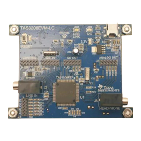
TAS3208EVM-LC PCB Component Mapping www.ti.com TAS3208EVM-LC PCB Component Mapping Input TUSB3210 (underside) Analog Output Header Control Header I S Input Header I S Output Header Stereo Line In Jack Headphone Output TAS3208 Figure 1-2. Component Mapping Figure 1-3. Printed Circuit Assembly Overview SLEU097 –... -
Page 11: Quick Setup Guide
Quick Setup Guide This chapter provides a step-by-step guide to configuring the TAS3208EVM-LC for device evaluation. This chapter describes the TAS3208EVM-LC board in regard to power supply requirements and system interfaces. The chapter provides information regarding handling, unpacking, and absolute operating conditions. -
Page 12: Unpacking The Evm
Center nearest you to inquire about a replacement. Power Supply Setup The TAS3208EVM-LC is powered via the universal serial bus (USB) connection from the host PC. No additional power supplies are needed to evaluate the device. PurePath GDE Software Installation The TAS3208 is programmed and configured using Texas Instruments PurePath Studio. -
Page 13: Developing The Process Flow On The Evm
SAP clock for master mode operation. 2.4.2 Configuring the EVM After completing the software installation, connect the USB cable to J7 on the TAS3208EVM-LC board. This connection powers the EVM and automatically enumerates the TUSB3210 USB Serial Controller required for communication between the host PC and the TAS3208 Digital Audio Processor. -
Page 14: Master/Slave Mode Operation
C clocks are still internally derived from the external crystal. Serial Digital Audio is input in to the TAS3208EVM-LC via the Serial Digital Input header (J1). Analog signals are input via the analog input header (J4), or the line in jack (J2). -
Page 15: Running The Process Flow
The GDE generates and assembles the code for the process flow, downloads it to the EVM, then resets the TAS3208EVM-LC board. At this point the GDE switches from Edit Mode to Run Mode, and streams audio from input to output. - Page 16 Quick Setup Guide SLEU097 – April 2008 Submit Documentation Feedback...
-
Page 17: System Interfaces
Chapter 3 SLEU097 – April 2008 System Interfaces This chapter describes the TAS3208EVM-LC board in regard to system interfaces....................Topic Page ............... Digital Audio Interface .............. Analog Audio Interface ............... Control Interface SLEU097 – April 2008 System Interfaces Submit Documentation Feedback... -
Page 18: Digital Audio Interface
Digital Audio Interface www.ti.com Digital Audio Interface The digital audio interface contains the digital I S clocks and data. Please refer to the TAS3208 Data Manual for signal timing an overview of the I S protocol. 3.1.1 Digital Input Header Table 3-1. -
Page 19: Analog Audio Interface
Analog Audio Interface www.ti.com Analog Audio Interface 3.2.1 Analog Output Header Table 3-3. Analog Output Interface (J5) HEADER SIGNAL NAME SCHEMATIC NET NAME PIN ASSIGNMENT Right headphone amp output Analog ground Left headphone amp output Analog ground Digital-to-analog 2 right output DAC2R Analog ground Digital-to-analog 2 left output... -
Page 20: Control Interface
Control Interface www.ti.com Control Interface This interface connects the TAS3208 to an external controller. This is a general purpose interface. Table 3-5. Control Interface (J6) HEADER SIGNAL NAME SCHEMATIC NET NAME PIN ASSIGNMENT Ground Not connected Mute General purpose input/output 2 GPIO2 General purpose input/output 1 GPIO1... -
Page 21: Important Notices
EVALUATION BOARD/KIT IMPORTANT NOTICE Texas Instruments (TI) provides the enclosed product(s) under the following conditions: This evaluation board/kit is intended for use for ENGINEERING DEVELOPMENT, DEMONSTRATION, OR EVALUATION PURPOSES ONLY and is not considered by TI to be a finished end-product fit for general consumer use. Persons handling the product(s) must have electronics training and observe good engineering practice standards. - Page 22 EVM schematic located in the EVM User's Guide. When placing measurement probes near these devices during operation, please be aware that these devices may be very warm to the touch. Mailing Address: Texas Instruments, Post Office Box 655303, Dallas, Texas 75265 Copyright 2008, Texas Instruments Incorporated...
- Page 23 IMPORTANT NOTICE Texas Instruments Incorporated and its subsidiaries (TI) reserve the right to make corrections, modifications, enhancements, improvements, and other changes to its products and services at any time and to discontinue any product or service without notice. Customers should obtain the latest relevant information before placing orders and should verify that such information is current and complete.
- Page 24 Mouser Electronics Authorized Distributor Click to View Pricing, Inventory, Delivery & Lifecycle Information: Texas Instruments TAS3208EVM-LC...
Need help?
Do you have a question about the TAS3208EVM-LC and is the answer not in the manual?
Questions and answers