Advertisement
Quick Links
www.ti.com
EVM User's Guide: TAC5412Q15B5EVM-K TAC5411Q15B5EVM-K
TAA5412Q15B5EVM-K
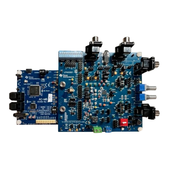
TAx5x1xQ15B5EVM-K Evaluation Module
Description
This user guide describes the functionality of
the TAC5412Q15B5EVM-K, TAC5411Q15B5EVM,
or TAA5412Q15B5EVM-K evaluation kit. The
TAx5x1xQ15B5EVM-K evaluation module (EVM)
allows the user to test the capabilities of
Texas Instruments' two-channel high-performance
ADC TAA5412-Q1, a two-channel TAC5412-Q1 or
TAC5411-Q1, a single-channel high-performance
codec. Other variants listed in
supported where users will replace the U1 unit with
the device of interest. The evaluation module is paired
with the AC-MB, a flexible motherboard that provides
power, control, and digital audio data to the evaluation
module.
Get Started
1. Order the EVM from the TAx5x12 product folder.
2. Download the latest TAx5x12 data sheet.
3. Request access and download the PPC3 GUI
from the TAx5x12 product folder.
SLAAEC6 – OCTOBER 2023
Submit Document Feedback
Table 1-1
are also
Copyright © 2023 Texas Instruments Incorporated
Features
•
Complete evaluation kit for the TAC5x12-Q1
(two-channel codec), TAC5x11-Q1 (single-channel
codec), or TAA5412-Q1 (two-channel ADC).
•
High-performance mono/stereo codec dynamic
range: 120 dB DAC and 110 dB ADC or standard
performance 106 dB DAC and 102 dB ADC
•
On-board microphones provided for voice
recording testing
•
Direct access to digital audio signals and control
interface for simple end-system integration
•
USB connection to PC provides power, control,
and streaming audio data for easy evaluation
•
On-board diagnostic scenarios for analog audio
input
Applications
•
Emergency E-Call
•
Telematics control unit
•
Automotive active noise cancellation
•
Automotive head units
TAx5x1xQ15B5EVM-K Evaluation Module
Description
1
Advertisement

Subscribe to Our Youtube Channel
Related Manuals for Texas Instruments TA 5 1 Q15B5EVM-K Series


Summary of Contents for Texas Instruments TA 5 1 Q15B5EVM-K Series
- Page 1 Telematics control unit 3. Request access and download the PPC3 GUI • Automotive active noise cancellation from the TAx5x12 product folder. • Automotive head units SLAAEC6 – OCTOBER 2023 TAx5x1xQ15B5EVM-K Evaluation Module Submit Document Feedback Copyright © 2023 Texas Instruments Incorporated...
- Page 2 Table 1-1. TAx5x1x-Q1 Family Device ADC DR (dB) DAC DR (dB) Feature TAC5412-Q1 Stereo codec TAC5411-Q1 Mono codec TAC5312-Q1 Stereo codec TAC5311-Q1 Mono codec TAA5412-Q1 Stereo ADC TAx5x1xQ15B5EVM-K Evaluation Module SLAAEC6 – OCTOBER 2023 Submit Document Feedback Copyright © 2023 Texas Instruments Incorporated...
- Page 3 C and SPI MOSI Test Points SCLK /POR Power-On Reset /SS 1-2 /RESET /RESET /RESET_SW Main Rest AC_MB_EVM_Connector AC_MB Figure 2-1. TAx5x1xQ1 EVM Block Diagram SLAAEC6 – OCTOBER 2023 TAx5x1xQ15B5EVM-K Evaluation Module Submit Document Feedback Copyright © 2023 Texas Instruments Incorporated...
- Page 4 The default settings for the USB audio interface are 32-bit frame size, 48-kHz sampling rate, BCLK and FSYNC ratio of 256, and the format is time-division multiplexing (TDM). TAx5x1xQ15B5EVM-K Evaluation Module SLAAEC6 – OCTOBER 2023 Submit Document Feedback Copyright © 2023 Texas Instruments Incorporated...
- Page 5 (DAC) is connected to the AC-MB, providing an analog input for quick evaluation. In auxiliary analog audio mode, the audio serial interface format is fixed to a 24-bit, 48-kHz, I2S mode. SLAAEC6 – OCTOBER 2023 TAx5x1xQ15B5EVM-K Evaluation Module Submit Document Feedback Copyright © 2023 Texas Instruments Incorporated...
- Page 6 Odd-numbered pins are signal-carrying; even- numbered pins are connected to ground. Figure 2-6. AC-MB Connection with External Audio Serial Interface TAx5x1xQ15B5EVM-K Evaluation Module SLAAEC6 – OCTOBER 2023 Submit Document Feedback Copyright © 2023 Texas Instruments Incorporated...
- Page 7 LDOs are correct. The USB READY LED indicates a successful USB communication between the AC-MB and the host computer. SLAAEC6 – OCTOBER 2023 TAx5x1xQ15B5EVM-K Evaluation Module Submit Document Feedback Copyright © 2023 Texas Instruments Incorporated...
- Page 8 The INxP and INxM pins of the TAx5x1x-Q1 can optionally connect to onboard microphones for quick evaluation of a microphone in AC or DC-coupled modes. Jumper configuration details can be found in Table 2-1. TAx5x1xQ15B5EVM-K Evaluation Module SLAAEC6 – OCTOBER 2023 Submit Document Feedback Copyright © 2023 Texas Instruments Incorporated...
- Page 9 On-board Electret J4, J5, J8, J11, J6, J15, J16 Refer to B0_P0_R80, Condenser J12 (1-2), J20, J21 Microphone data B0_P1_R115 Microphone sheet (ECM) Differential, AC-coupled SLAAEC6 – OCTOBER 2023 TAx5x1xQ15B5EVM-K Evaluation Module Submit Document Feedback Copyright © 2023 Texas Instruments Incorporated...
- Page 10 J7, J13, J14, J22, Refer to the B0_P0_R85, Analog MEMS J23, J8 (DUT Microphone data B0_P1_R115 microphone, DC- MICBIAS is not sheet. coupled used) TAx5x1xQ15B5EVM-K Evaluation Module SLAAEC6 – OCTOBER 2023 Submit Document Feedback Copyright © 2023 Texas Instruments Incorporated...
- Page 11 The TAx5x1x-Q1 evaluation module has several output configuration options and offers flexibility to allow the user to evaluate the device with different load conditions and configurations. The different configurations are highlighted in this section. SLAAEC6 – OCTOBER 2023 TAx5x1xQ15B5EVM-K Evaluation Module Submit Document Feedback Copyright © 2023 Texas Instruments Incorporated...
- Page 12 3, 6, 9, 12 10 kΩ 0.4 W B0_P0_R101 Figure 2-12. TAC5x12-Q1 Analog Output Connections For TAC5411-Q1 or TAC5311-Q1, OUT2 components are not populated. TAx5x1xQ15B5EVM-K Evaluation Module SLAAEC6 – OCTOBER 2023 Submit Document Feedback Copyright © 2023 Texas Instruments Incorporated...
- Page 13 A short to VBAT test requires an external voltage source connected to VBAT through J26 or onboard VBAT through J27. If onboard VBAT is used, populate the J47 pin 1-2 jumper to enable the U4 switch regulator. SLAAEC6 – OCTOBER 2023 TAx5x1xQ15B5EVM-K Evaluation Module Submit Document Feedback Copyright © 2023 Texas Instruments Incorporated...
- Page 14 2.3.3 Shorted Input Pins Setup Shorted input diagnostic testing can be performed for differential inputs only. Figure 2-17. Short to Input Diagnostic Test Setup TAx5x1xQ15B5EVM-K Evaluation Module SLAAEC6 – OCTOBER 2023 Submit Document Feedback Copyright © 2023 Texas Instruments Incorporated...
- Page 15 GPIO1 can be configured as either the WCLK, BCLK, DIN, or DOUT in the controller or peripheral mode, as shown in Figure 2-19. Figure 2-19. GPIO1 Configuration SLAAEC6 – OCTOBER 2023 TAx5x1xQ15B5EVM-K Evaluation Module Submit Document Feedback Copyright © 2023 Texas Instruments Incorporated...
- Page 16 (ASI2). In Audio Serial Interface, GPI1A can be configured as either the WCLK, BCLK, or DIN in peripheral mode, as shown in Figure 2-21. Figure 2-21. GPI1A Configuration TAx5x1xQ15B5EVM-K Evaluation Module SLAAEC6 – OCTOBER 2023 Submit Document Feedback Copyright © 2023 Texas Instruments Incorporated...
- Page 17 (pull-up to AVDD). Header J73 needs to be populated on pin 1-2. Device Address (7-bit Device Address (8-bit ADDRA Level Addressing) Addressing) AVDD 0x51 0xA2 0x50 0xA0 SLAAEC6 – OCTOBER 2023 TAx5x1xQ15B5EVM-K Evaluation Module Submit Document Feedback Copyright © 2023 Texas Instruments Incorporated...
- Page 18 SASI with the external audio instrument, remove the jumpers on header J43 and place jumper on header J67 pin 2-3, as shown in Figure 2-24. Figure 2-24. External Audio Serial Interface Connection TAx5x1xQ15B5EVM-K Evaluation Module SLAAEC6 – OCTOBER 2023 Submit Document Feedback Copyright © 2023 Texas Instruments Incorporated...
- Page 19 Open the PPC3 installer and follow the instructions in the setup wizard. 3.2.1 USB Audio Setup Note When using the USB audio interface, the Texas Instruments USB audio device control panel, shown in Figure 3-2, opens with the input setting configured for eight channels, 32 bits. For USB audio, 32-bit mode must also be used on the EVM.
- Page 20 Choose the 1 device radio button and click New. Figure 3-4. Select Device Configuration The GUI opens to the default Device Config tab, as shown below. TAx5x1xQ15B5EVM-K Evaluation Module SLAAEC6 – OCTOBER 2023 Submit Document Feedback Copyright © 2023 Texas Instruments Incorporated...
- Page 21 Users can first configure the device and then activate the PPC3. Once activated, some controls are grayed out until the ACTIVE button is deactivated. Figure 3-8. Activate GUI SLAAEC6 – OCTOBER 2023 TAx5x1xQ15B5EVM-K Evaluation Module Submit Document Feedback Copyright © 2023 Texas Instruments Incorporated...
- Page 22 3-9, contains all of the tools used to configure and program the TAx5x1x-Q1 EVM. This view has tabs for each device configuration and is described in this section. Figure 3-9. Configuration View TAx5x1xQ15B5EVM-K Evaluation Module SLAAEC6 – OCTOBER 2023 Submit Document Feedback Copyright © 2023 Texas Instruments Incorporated...
- Page 23 IO and MIC Bias levels. Input channel 3 and channel 4 are associated with the PDM input channels. Figure 3-10. Device Config Tab SLAAEC6 – OCTOBER 2023 TAx5x1xQ15B5EVM-K Evaluation Module Submit Document Feedback Copyright © 2023 Texas Instruments Incorporated...
- Page 24 Figure 3-11. Record Config Tab Figure 3-12. PDM Record Config Tab TAx5x1xQ15B5EVM-K Evaluation Module SLAAEC6 – OCTOBER 2023 Submit Document Feedback Copyright © 2023 Texas Instruments Incorporated...
- Page 25 3.3.2.3.1 Configuring Primary Audio Serial Bus Figure 3-13. Primary Audio Serial Bus - Page 1 Figure 3-14. Primary Audio Serial Bus TX - Page 2 SLAAEC6 – OCTOBER 2023 TAx5x1xQ15B5EVM-K Evaluation Module Submit Document Feedback Copyright © 2023 Texas Instruments Incorporated...
- Page 26 Software www.ti.com Figure 3-15. Primary Audio Serial Bus RX - Page 3 TAx5x1xQ15B5EVM-K Evaluation Module SLAAEC6 – OCTOBER 2023 Submit Document Feedback Copyright © 2023 Texas Instruments Incorporated...
- Page 27 Figure 3-16. Secondary Audio Serial Bus Page 1 Figure 3-17. Secondary Audio Serial Bus TX - Page 2 SLAAEC6 – OCTOBER 2023 TAx5x1xQ15B5EVM-K Evaluation Module Submit Document Feedback Copyright © 2023 Texas Instruments Incorporated...
- Page 28 Output (GPIO1) in the TAx5x1x-Q1 devices. These general-purpose input/output drivers also provide several multiplexing functions, and the selection can also be configured in this tab. TAx5x1xQ15B5EVM-K Evaluation Module SLAAEC6 – OCTOBER 2023 Submit Document Feedback Copyright © 2023 Texas Instruments Incorporated...
- Page 29 Software Figure 3-20. GPIO and Interrupts Tab SLAAEC6 – OCTOBER 2023 TAx5x1xQ15B5EVM-K Evaluation Module Submit Document Feedback Copyright © 2023 Texas Instruments Incorporated...
- Page 30 PPC3, or coefficients from an external filter design tool can be manually entered. Each biquad can be configured individually, and then the gain and phase TAx5x1xQ15B5EVM-K Evaluation Module SLAAEC6 – OCTOBER 2023 Submit Document Feedback Copyright © 2023 Texas Instruments Incorporated...
- Page 31 AGC configuration to become active. These software controls are grayed out and inactive while the device is in active mode. SLAAEC6 – OCTOBER 2023 TAx5x1xQ15B5EVM-K Evaluation Module Submit Document Feedback Copyright © 2023 Texas Instruments Incorporated...
- Page 32 Software www.ti.com Figure 3-25. Automatic Gain Control (AGC) Tab TAx5x1xQ15B5EVM-K Evaluation Module SLAAEC6 – OCTOBER 2023 Submit Document Feedback Copyright © 2023 Texas Instruments Incorporated...
- Page 33 Figure 3-26. Voice/Ultrasonic Auto Detection 3.3.2.5.5 Mixer Tab The TAx5x1x-Q1 devices support several mixing features; settings are available in this tab. Figure 3-27. Mixer Tab SLAAEC6 – OCTOBER 2023 TAx5x1xQ15B5EVM-K Evaluation Module Submit Document Feedback Copyright © 2023 Texas Instruments Incorporated...
- Page 34 Figure 3-28. Tone Generation 3.3.2.5.7 Limiter Tab Various device limiters like brown out and temperature are available in this tab. Figure 3-29. Limiter Tab TAx5x1xQ15B5EVM-K Evaluation Module SLAAEC6 – OCTOBER 2023 Submit Document Feedback Copyright © 2023 Texas Instruments Incorporated...
- Page 35 The register map view provides a view of page 0, page 1, and page 3 of the register map. Figure 3-31. Register Map View SLAAEC6 – OCTOBER 2023 TAx5x1xQ15B5EVM-K Evaluation Module Submit Document Feedback Copyright © 2023 Texas Instruments Incorporated...
- Page 36 I2C monitor window opens, as shown in the figure below. Click on the I/O button to access the input/output panel. Figure 3-32. I2C Monitor Window Figure 3-33. I2C Monitor I/O Window TAx5x1xQ15B5EVM-K Evaluation Module SLAAEC6 – OCTOBER 2023 Submit Document Feedback Copyright © 2023 Texas Instruments Incorporated...
- Page 37 # 1 data input and 1 data output for PASI w a0 1a 70 # PASI I2S, 32-bit format w a0 1e 20 # PASI Ch1 on Left slot 0 SLAAEC6 – OCTOBER 2023 TAx5x1xQ15B5EVM-K Evaluation Module Submit Document Feedback Copyright © 2023 Texas Instruments Incorporated...
- Page 38 # Enable Input Ch1 and Ch2, disable output channels w a0 78 A0 # Power up ADC and MICBIAS • Target mode differential DC-couple recording with PASI TAx5x1xQ15B5EVM-K Evaluation Module SLAAEC6 – OCTOBER 2023 Submit Document Feedback Copyright © 2023 Texas Instruments Incorporated...
- Page 39 # Configure OUT2P as mono single-ended from DAC2 w a0 6c 20 # Configure OUT2P LINEOUT 0dB audio band w a0 6d 20 # Configure 2Vrms Differential SLAAEC6 – OCTOBER 2023 TAx5x1xQ15B5EVM-K Evaluation Module Submit Document Feedback Copyright © 2023 Texas Instruments Incorporated...
- Page 40 # Configure OUT1P LINEOUT 0dB audio band w a0 66 20 # Configure OUT1M LINEOUT 0dB 2Vrms Differential w a0 6b 20 # Configure OUT2P/M as differential from DAC2 TAx5x1xQ15B5EVM-K Evaluation Module SLAAEC6 – OCTOBER 2023 Submit Document Feedback Copyright © 2023 Texas Instruments Incorporated...
- Page 41 # Set page 1 w a0 73 d0 # Set MICBIAS = 9V w a0 46 80 # Enable IN1P and IN1M Scan for diagnostic SLAAEC6 – OCTOBER 2023 TAx5x1xQ15B5EVM-K Evaluation Module Submit Document Feedback Copyright © 2023 Texas Instruments Incorporated...
- Page 42 Figure 5-1. System Overview 6 Hardware Design Files This section provides the schematics, layout examples, and bill of materials (BOM) for each TAC541x-Q1 EVM variant. TAx5x1xQ15B5EVM-K Evaluation Module SLAAEC6 – OCTOBER 2023 Submit Document Feedback Copyright © 2023 Texas Instruments Incorporated...
- Page 43 Hardware Design Files 6.1 TAC5412-Q1 EVM Schematic Figure 6-1. TAC5412-Q1 EVM Main DUT Schematic SLAAEC6 – OCTOBER 2023 TAx5x1xQ15B5EVM-K Evaluation Module Submit Document Feedback Copyright © 2023 Texas Instruments Incorporated...
- Page 44 Hardware Design Files www.ti.com Figure 6-2. TAC5412-Q1 EVM Connectors and Supporting Circuitry Schematic TAx5x1xQ15B5EVM-K Evaluation Module SLAAEC6 – OCTOBER 2023 Submit Document Feedback Copyright © 2023 Texas Instruments Incorporated...
- Page 45 Hardware Design Files 6.2 TAC5411-Q1 EVM Schematic Figure 6-3. TAC5411-Q1 EVM Main DUT Schematic SLAAEC6 – OCTOBER 2023 TAx5x1xQ15B5EVM-K Evaluation Module Submit Document Feedback Copyright © 2023 Texas Instruments Incorporated...
- Page 46 Hardware Design Files www.ti.com Figure 6-4. TAC5411-Q1 EVM Connectors and Supporting Circuitry Schematic TAx5x1xQ15B5EVM-K Evaluation Module SLAAEC6 – OCTOBER 2023 Submit Document Feedback Copyright © 2023 Texas Instruments Incorporated...
- Page 47 Corporation +125°C Automotive CAP, CERM, 10 µF, 25 V, C4, C5, C7, +/- 5%, X7R, C1206C106J 10uF 1206 Kemet AEC-Q200 3RACAUTO Grade 1, 1206 SLAAEC6 – OCTOBER 2023 TAx5x1xQ15B5EVM-K Evaluation Module Submit Document Feedback Copyright © 2023 Texas Instruments Incorporated...
- Page 48 Surface onics Mount 8- SOIC LED, Green, LTST- Green LED_0805 Lite-On C170KGKT Diode, 20 V Schottky, 20 B220A-13-F Diodes Inc. V, 2 A, SMA TAx5x1xQ15B5EVM-K Evaluation Module SLAAEC6 – OCTOBER 2023 Submit Document Feedback Copyright © 2023 Texas Instruments Incorporated...
- Page 49 6.91103E+11 Wurth _POS2 3.20 mm ID, 9.00 mm OD (RCA) Phono J2, J3, J38, CONN_RCA_ (RCA) Jack RCJ-2223 CUI Devices DUAL Mono Connector Solder SLAAEC6 – OCTOBER 2023 TAx5x1xQ15B5EVM-K Evaluation Module Submit Document Feedback Copyright © 2023 Texas Instruments Incorporated...
- Page 50 6 x 2 Header Samtec Gold, TH Relay, SPST- Omron G3VM-31HR( NO (1 Form 6.3 x 4.4 mm Electronic TR05) A), 4 A, SMD Components TAx5x1xQ15B5EVM-K Evaluation Module SLAAEC6 – OCTOBER 2023 Submit Document Feedback Copyright © 2023 Texas Instruments Incorporated...
- Page 51 0.25 W, AEC- PMR03EZPJ0 0603 Rohm R38, R39, Q200 Grade 0, 0603 RES, 16.0, R21, R24, ERJ- 1%, 0.5 W, 0805 Panasonic R27, R30 P06F16R0V 0805 SLAAEC6 – OCTOBER 2023 TAx5x1xQ15B5EVM-K Evaluation Module Submit Document Feedback Copyright © 2023 Texas Instruments Incorporated...
- Page 52 0603 Res POT Carbon Element 100 PTH_POT_9 PTD902-2015 R50, R51 100 kΩ kΩ 20% 1/20 MM50_24MM Bourns F-B104 W/1/40 W PC Pins Thru- Hole TAx5x1xQ15B5EVM-K Evaluation Module SLAAEC6 – OCTOBER 2023 Submit Document Feedback Copyright © 2023 Texas Instruments Incorporated...
- Page 53 SH53, SH54, SH55, SH56, SH57, SH58, SH59, SH60 Dip Switch SPST 12 Position Through Hole DIP24 206-12ST Slide (Standard) Actuator 50 mA 24 VDC SLAAEC6 – OCTOBER 2023 TAx5x1xQ15B5EVM-K Evaluation Module Submit Document Feedback Copyright © 2023 Texas Instruments Incorporated...
- Page 54 SPH8878LR5 SPH1878LR5 Knowles Knowles - 3.6 V Omnidirection al (-44 dB ± 0.5 dB SPL) Solder Pads TCA9416DT TCA9416DT Texas X2SON8 M X2SON8 Instruments TAx5x1xQ15B5EVM-K Evaluation Module SLAAEC6 – OCTOBER 2023 Submit Document Feedback Copyright © 2023 Texas Instruments Incorporated...
- Page 55 R34, R36 48.7k AEC-Q200 0805 Vishay-Dale 8K7FKEA Grade 0, 0805 RES, 21.5 k, 1%, 0.125 W, CRCW08052 21.5k AEC-Q200 0805 Vishay-Dale 1K5FKEA Grade 0, 0805 SLAAEC6 – OCTOBER 2023 TAx5x1xQ15B5EVM-K Evaluation Module Submit Document Feedback Copyright © 2023 Texas Instruments Incorporated...
- Page 56 2.2µF uF 35 V X7R 1206 225K160AE 10% 1206 CAP, CERM, 1 uF, 35 V, +/- C1608X7R1V C2, C16 0603 10%, X7R, 105K080AC 0603 TAx5x1xQ15B5EVM-K Evaluation Module SLAAEC6 – OCTOBER 2023 Submit Document Feedback Copyright © 2023 Texas Instruments Incorporated...
- Page 57 220 pF 0603 Kemet +/- 5%, C0G/ 5GACTU NP0, 0603 CAP, CERM, 10 uF, 25 V, GRM31CR71 10uF 1206 MuRata +/- 10%, X7R, E106KA12L 1206 SLAAEC6 – OCTOBER 2023 TAx5x1xQ15B5EVM-K Evaluation Module Submit Document Feedback Copyright © 2023 Texas Instruments Incorporated...
- Page 58 Keystone diameter and Head Dia a 4-40 threading STANDOFF STANDOFF H3, H4 4804 Keystone 4-40 NYLON 4-40 NYLON 3/4" 3/4" CONN_TERM 6.91103E+11 Wurth _POS2 TAx5x1xQ15B5EVM-K Evaluation Module SLAAEC6 – OCTOBER 2023 Submit Document Feedback Copyright © 2023 Texas Instruments Incorporated...
- Page 59 7x2 Header Samtec Gold, TH Header, TSW-104-07- J52, J66 100mil, 4x2, 4x2 Header Samtec Gold, TH Header, TSW-106-07- 100mil, 6x2, 6x2 Header Samtec Gold, TH SLAAEC6 – OCTOBER 2023 TAx5x1xQ15B5EVM-K Evaluation Module Submit Document Feedback Copyright © 2023 Texas Instruments Incorporated...
- Page 60 Vishay-Dale 0.05 W, 0201 000Z0ED R13, R14, RES, 0, 0%, R15, R16, 0.25 W, AEC- PMR03EZPJ0 0603 Rohm R38, R39, Q200 Grade 0, 0603 TAx5x1xQ15B5EVM-K Evaluation Module SLAAEC6 – OCTOBER 2023 Submit Document Feedback Copyright © 2023 Texas Instruments Incorporated...
- Page 61 CRCW06038 86.6k AEC-Q200 0603 Vishay-Dale 6K6FKEA Grade 0, 0603 RES, 10.2 k, 1%, 0.1 W, CRCW06031 10.2k AEC-Q200 0603 Vishay-Dale 0K2FKEA Grade 0, 0603 SLAAEC6 – OCTOBER 2023 TAx5x1xQ15B5EVM-K Evaluation Module Submit Document Feedback Copyright © 2023 Texas Instruments Incorporated...
- Page 62 24-VDC Switch, Tactile, SPST- Switch, TL1015AF160 E-Switch NO, 0.05A, 4.4x2x2.9 mm 12-V, SMT Switch, DPDT, 0.15 A, 9.65x9.65mm 76STD01T Grayhill 30 VDC, TH TAx5x1xQ15B5EVM-K Evaluation Module SLAAEC6 – OCTOBER 2023 Submit Document Feedback Copyright © 2023 Texas Instruments Incorporated...
- Page 63 (UQFN-12) Digital, PDM Microphone MEMS (Silicon) SMT_MIC_2 SPH0655LM4 U8, U9 Omnidirection MM65_3MM5 Knowles al (-37 dB ±1 dB @ 94 dB SPL) Solder Pads SLAAEC6 – OCTOBER 2023 TAx5x1xQ15B5EVM-K Evaluation Module Submit Document Feedback Copyright © 2023 Texas Instruments Incorporated...
- Page 64 2.54mm, 2x2, PBC02DAAN Connector Gold, TH Solutions RES, 1.1 k, 5%, 0.1 W, CRCW06031 R2, R4 1.1k AEC-Q200 0603 Vishay-Dale K10JNEA Grade 0, 0603 TAx5x1xQ15B5EVM-K Evaluation Module SLAAEC6 – OCTOBER 2023 Submit Document Feedback Copyright © 2023 Texas Instruments Incorporated...
- Page 65 Bourns F-B104 1/20W/1/40W PC Pins Thru- Hole 10k ±5% 0.063W, 1/16W Chip Resistor 0402 RC0402JR-13 0402 Yageo (1005 Metric) 10KL Moisture Resistant Thick Film SLAAEC6 – OCTOBER 2023 TAx5x1xQ15B5EVM-K Evaluation Module Submit Document Feedback Copyright © 2023 Texas Instruments Incorporated...
- Page 66 7 Hz - 36 kHz Analog Microphone MEMS (Silicon) 2.3 V SPH8878LR5 SPH1878LR5 Knowles Knowles - 3.6 V Omnidirection al (-44dB ± 0.5dB SPL) Solder Pads TAx5x1xQ15B5EVM-K Evaluation Module SLAAEC6 – OCTOBER 2023 Submit Document Feedback Copyright © 2023 Texas Instruments Incorporated...
- Page 67 Figure 6-5. TAC541x-Q1 EVM Top Silkscreen Figure 6-6. TAC541x-Q1 EVM Top Layer Figure 6-7. TAC541x-Q1 EVM Power Layer 1 Figure 6-8. TAC541x-Q1 EVM Power Layer 2 SLAAEC6 – OCTOBER 2023 TAx5x1xQ15B5EVM-K Evaluation Module Submit Document Feedback Copyright © 2023 Texas Instruments Incorporated...
- Page 68 Figure 6-9. TAC541x-Q1 EVM Ground Layer 1 Figure 6-10. TAC541x-Q1 EVM Ground Layer 2 Figure 6-11. TAC541x-Q1 EVM Signal Layer 1 Figure 6-12. TAC541x-Q1 EVM Signal Layer 2 TAx5x1xQ15B5EVM-K Evaluation Module SLAAEC6 – OCTOBER 2023 Submit Document Feedback Copyright © 2023 Texas Instruments Incorporated...
- Page 69 7 Additional Information 7.1 Trademarks PurePath ™ is a trademark of Texas Instruments. All trademarks are the property of their respective owners. 7.2 Cable References The following cables can be used for evaluation with external audio instruments like Audio Precision: •...
- Page 70 STANDARD TERMS FOR EVALUATION MODULES Delivery: TI delivers TI evaluation boards, kits, or modules, including any accompanying demonstration software, components, and/or documentation which may be provided together or separately (collectively, an “EVM” or “EVMs”) to the User (“User”) in accordance with the terms set forth herein.
- Page 71 www.ti.com Regulatory Notices: 3.1 United States 3.1.1 Notice applicable to EVMs not FCC-Approved: FCC NOTICE: This kit is designed to allow product developers to evaluate electronic components, circuitry, or software associated with the kit to determine whether to incorporate such items in a finished product and software developers to write software applications for use with the end product.
- Page 72 www.ti.com Concernant les EVMs avec antennes détachables Conformément à la réglementation d'Industrie Canada, le présent émetteur radio peut fonctionner avec une antenne d'un type et d'un gain maximal (ou inférieur) approuvé pour l'émetteur par Industrie Canada. Dans le but de réduire les risques de brouillage radioélectrique à...
- Page 73 www.ti.com EVM Use Restrictions and Warnings: 4.1 EVMS ARE NOT FOR USE IN FUNCTIONAL SAFETY AND/OR SAFETY CRITICAL EVALUATIONS, INCLUDING BUT NOT LIMITED TO EVALUATIONS OF LIFE SUPPORT APPLICATIONS. 4.2 User must read and apply the user guide and other available documentation provided by TI regarding the EVM prior to handling or using the EVM, including without limitation any warning or restriction notices.
- Page 74 Notwithstanding the foregoing, any judgment may be enforced in any United States or foreign court, and TI may seek injunctive relief in any United States or foreign court. Mailing Address: Texas Instruments, Post Office Box 655303, Dallas, Texas 75265 Copyright © 2023, Texas Instruments Incorporated...
- Page 75 TI products. TI’s provision of these resources does not expand or otherwise alter TI’s applicable warranties or warranty disclaimers for TI products. TI objects to and rejects any additional or different terms you may have proposed. IMPORTANT NOTICE Mailing Address: Texas Instruments, Post Office Box 655303, Dallas, Texas 75265 Copyright © 2023, Texas Instruments Incorporated...
Need help?
Do you have a question about the TA 5 1 Q15B5EVM-K Series and is the answer not in the manual?
Questions and answers