Table of Contents
Advertisement
Quick Links
This manual describes the operation of the TAS5755MEVM to evaluate the performance of the
TAS5755M integrated digital audio power amplifier. The main contents of this document are:
•
Details on properly connecting a TAS5755M evaluation module (EVM) and the details of the EVM
•
Details on installing and using the GUI to program the TAS5755MEVM
•
Quick-start guide for the common modes in which the TAS5755MEVM can be used
•
Details on using the audio processing features like EQ and DRC
......................................................................................................................
1
1.1
....................................................................................................................
2
2.1
2.2
3
3.1
3.2
3.3
3.4
3.5
3.6
3.7
4
4.1
4.2
4.3
5
5.1
5.2
5.3
1
2
3
4
5
6
7
8
9
10
11
12
13
TAS5755MEVM Evaluation Module
.....................................................................................................
................................................................................................
.....................................................................................................
.......................................................................................
...................................................................................
2
.............................................................................................
................................................................................................
.........................................................................................
..............................................................................
......................................................................................
2
....................................................................................
............................................................................................................
.....................................................................................................
...................................................................................
......................................................................................
....................................................................................................
....................................................................................
................................................................................................
..............................................................................................
..............................................................................................................
...............................................................................................................
...........................................................................................
.............................................................................................
........................................................................................
................................................................................
...................................................................................
Copyright © 2017, Texas Instruments Incorporated
SLOU481A - August 2017 - Revised October 2017
Contents
...................................................................
............................................................
.......................................................................
List of Figures
.....................................................................
...........................................................................
........................................................
User's Guide
2
3
4
4
7
8
8
9
10
12
13
15
16
17
17
17
17
18
18
19
20
2
3
4
5
5
6
6
8
9
10
10
11
11
1
Advertisement
Table of Contents

Related Manuals for Texas Instruments TAS5755MEVM


Summary of Contents for Texas Instruments TAS5755MEVM
-
Page 1: Table Of Contents
User's Guide SLOU481A – August 2017 – Revised October 2017 TAS5755MEVM Evaluation Module This manual describes the operation of the TAS5755MEVM to evaluate the performance of the TAS5755M integrated digital audio power amplifier. The main contents of this document are: •... -
Page 2: Overview
All trademarks are the property of their respective owners. Overview The TAS5755M evaluation module demonstrates the TAS5755M device from Texas Instruments. The TAS5755M combines a high-performance PWM processor with a class-D audio power amplifier. This EVM can be configured with two single-ended (SE) speakers with a BTL subwoofers (2.1) or two bridge-tied speakers (BTL) (2.0). -
Page 3: Tas5755Mevm And Mc57Xxpsia Features
TAS5755 2CH Analog Input Subwoofer From Other Source/ Digital Out Copyright © 2017, Texas Instruments Incorporated Figure 2. Complete System and EVM Signal Path Overview TAS5755MEVM and MC57xxPSIA Features The EVM and MC57xxPSIA have the following features: • Channel evaluation module design •... -
Page 4: Installation
Optical or coaxial cable for SPDIF interface based on signal source • USB cable • EVM software • Speakers or loads for outputs TAS5755MEVM Evaluation Module SLOU481A – August 2017 – Revised October 2017 Submit Documentation Feedback Copyright © 2017, Texas Instruments Incorporated... -
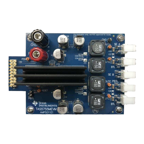
Page 5: Evm Board Speaker Outputs
Installation www.ti.com Figure 4. EVM Board Speaker Outputs The following sections describe the TAS5755MEVM board in regards to power supply (PSU) and system interfaces. 2.1.1 Connecting the TAS5755MEVM to MC57xxPSIA On the right side of the MC57xxPSIA is a terminal block and another is located on the left of the TAS5755MEVM (labeled J1). -
Page 6: Btl Connection
BTL rather than PBTL mode is enabled. When connecting a speaker in SE mode, connect the TAS5755MEVM speaker to one of the two SE connectors labeled SE A (J2) and SE B (J4). When connecting a speaker in BTL mode, connect the speaker to one of the two BLT connectors labeled BTL AB (J3) and BTL CD (J6). -
Page 7: Software Installation
2.1.7 Board Power-Up General Guidelines Connect the MC57xxPSIA and the TAS5755MEVM boards by locating pin 1 on each board, indicated by a small white triangle. The MC57xxPSIA plugs down onto the TAS5755MEVM board (that is, the TAS5755MEVM board fits underneath the MC57xxPSIA board). Pin 1 on each board must be connected to each other. -
Page 8: Using The Gui Software
Figure 8. TAS5755M DAP Block Diagram Launching the GUI interface The GUI interface can be opened by clicking on the TAS57X1 GDE icon under the Texas Instruments Inc title in the start program menu. NOTE: The PPSI2C variable should be set before the GUI interface (or the Memory Tool) is opened. -
Page 9: Setting The I 2 C Device Address
9. By default the EVM device address is 34 so the address should be changed by entering 34 and clicking change. Figure 9. Changing the Device Address SLOU481A – August 2017 – Revised October 2017 TAS5755MEVM Evaluation Module Submit Documentation Feedback Copyright © 2017, Texas Instruments Incorporated... -
Page 10: Initializing The Device
(2.0 or 2.1), and so forth, can also be specified using this menu. Figure 11. Zoomed-In Snapshot of the Configuration Drop-Down Menu TAS5755MEVM Evaluation Module SLOU481A – August 2017 – Revised October 2017 Submit Documentation Feedback Copyright © 2017, Texas Instruments Incorporated... -
Page 11: Initiating Connect From The Target Menu
GUI window. After completing these basic operations, the device can now stream audio. Figure 13. Toggling Shut-Down and Mute States SLOU481A – August 2017 – Revised October 2017 TAS5755MEVM Evaluation Module Submit Documentation Feedback Copyright © 2017, Texas Instruments Incorporated... -
Page 12: Using Eq Function
Finally, when the Apply button is clicked, the bi-quad registers of the device are updated with the programmed settings. Figure 15. EQ-Tool Filter Creation Window TAS5755MEVM Evaluation Module SLOU481A – August 2017 – Revised October 2017 Submit Documentation Feedback Copyright © 2017, Texas Instruments Incorporated... -
Page 13: Using The Drc Function
17. To use the DRC function in the GUI, update the DRC control to the Enabled state. Note that the DRC-1 and DRC-2 have independent enable and disable controls. SLOU481A – August 2017 – Revised October 2017 TAS5755MEVM Evaluation Module Submit Documentation Feedback Copyright © 2017, Texas Instruments Incorporated... - Page 14 Time Constants in the DRC customization tool. The Time Constants window snap shot is shown in Figure TAS5755MEVM Evaluation Module SLOU481A – August 2017 – Revised October 2017 Submit Documentation Feedback Copyright © 2017, Texas Instruments Incorporated...
-
Page 15: Using The Mixer And Scaler Nodes
0x51 is selected. Update the mixer configuration by changing the values in the properties window. Figure 20. Input, Output Mixer and Scaler Nodes SLOU481A – August 2017 – Revised October 2017 TAS5755MEVM Evaluation Module Submit Documentation Feedback Copyright © 2017, Texas Instruments Incorporated... -
Page 16: Using The I 2 C Memory Tool
Figure 21), or can also be launched stand-alone even when the GUI window is not opened, through the Windows → All-Programs → Texas Instruments Inc → I2C Memory tool option. The stand-alone capability is especially convenient when an existing I... -
Page 17: Jumpers And Control Utilities On The Mc57Xxpsia Board
LED4: Optical connection made • LED5: SPDIF signal locked • LED6: Not Populated • LED7: PDN switch (S4) is asserted SLOU481A – August 2017 – Revised October 2017 TAS5755MEVM Evaluation Module Submit Documentation Feedback Copyright © 2017, Texas Instruments Incorporated... -
Page 18: Board Layouts, Schematic, And Bill Of Materials
Board Layouts, Schematic, and Bill of Materials www.ti.com Board Layouts, Schematic, and Bill of Materials This section contains the TAS5755MEVM board layouts, schematic, and the bill of materials (BOM). TAS5755MEVM Board Layout Figure 22 shows the TAS5755MEVM top copper layer and... -
Page 19: Tas5755Mevm Schematic
AVSS STEST PGND 2200pF PGND PGND Heat Sink PGND TAS5755MDFD Copyright © 2017, Texas Instruments Incorporated Figure 24. TAS5755MEVM Schematic SLOU481A – August 2017 – Revised October 2017 TAS5755MEVM Evaluation Module Submit Documentation Feedback Copyright © 2017, Texas Instruments Incorporated... -
Page 20: Bill Of Materials
Board Layouts, Schematic, and Bill of Materials www.ti.com Bill of Materials Table 1 lists the BOM for this EVM. Table 1. TAS5755MEVM Bill Of Materials Value Description Package Reference Part Number Manufacturer Alternate Part Number Alternate Manufacturer 220uF CAP, AL, 220 µF, 35 V, ±20%, 0.16 ohm, SMD... - Page 21 Board Layouts, Schematic, and Bill of Materials www.ti.com Table 1. TAS5755MEVM Bill Of Materials (continued) Value Description Package Reference Part Number Manufacturer Alternate Part Number Alternate Manufacturer 0.33uF CAP, CERM, 0.33 µF, 50 V, ±10%, X7R, 1206 1206 GRM319R71H334KA01D Murata 330pF CAP, CERM, 330 pF, 50 V, ±5%, C0G/NP0, 0603...
- Page 22 Changes from Original (August 2017) to A Revision ..................... Page ..............• Changed images in the TAS5755MEVM Board Layout section........................• Changed schematic..........................• Changed BOM. Revision History SLOU481A – August 2017 – Revised October 2017 Submit Documentation Feedback Copyright © 2017, Texas Instruments Incorporated...
- Page 23 STANDARD TERMS FOR EVALUATION MODULES Delivery: TI delivers TI evaluation boards, kits, or modules, including any accompanying demonstration software, components, and/or documentation which may be provided together or separately (collectively, an “EVM” or “EVMs”) to the User (“User”) in accordance with the terms set forth herein.
- Page 24 FCC Interference Statement for Class B EVM devices NOTE: This equipment has been tested and found to comply with the limits for a Class B digital device, pursuant to part 15 of the FCC Rules. These limits are designed to provide reasonable protection against harmful interference in a residential installation.
- Page 25 【無線電波を送信する製品の開発キットをお使いになる際の注意事項】 開発キットの中には技術基準適合証明を受けて いないものがあります。 技術適合証明を受けていないもののご使用に際しては、電波法遵守のため、以下のいずれかの 措置を取っていただく必要がありますのでご注意ください。 1. 電波法施行規則第6条第1項第1号に基づく平成18年3月28日総務省告示第173号で定められた電波暗室等の試験設備でご使用 いただく。 2. 実験局の免許を取得後ご使用いただく。 3. 技術基準適合証明を取得後ご使用いただく。 なお、本製品は、上記の「ご使用にあたっての注意」を譲渡先、移転先に通知しない限り、譲渡、移転できないものとします。 上記を遵守頂けない場合は、電波法の罰則が適用される可能性があることをご留意ください。 日本テキサス・イ ンスツルメンツ株式会社 東京都新宿区西新宿6丁目24番1号 西新宿三井ビル 3.3.3 Notice for EVMs for Power Line Communication: Please see http://www.tij.co.jp/lsds/ti_ja/general/eStore/notice_02.page 電力線搬送波通信についての開発キットをお使いになる際の注意事項については、次のところをご覧ください。http:/ /www.tij.co.jp/lsds/ti_ja/general/eStore/notice_02.page 3.4 European Union 3.4.1 For EVMs subject to EU Directive 2014/30/EU (Electromagnetic Compatibility Directive): This is a class A product intended for use in environments other than domestic environments that are connected to a low-voltage power-supply network that supplies buildings used for domestic purposes.
- Page 26 Notwithstanding the foregoing, any judgment may be enforced in any United States or foreign court, and TI may seek injunctive relief in any United States or foreign court. Mailing Address: Texas Instruments, Post Office Box 655303, Dallas, Texas 75265 Copyright © 2017, Texas Instruments Incorporated...
- Page 27 IMPORTANT NOTICE FOR TI DESIGN INFORMATION AND RESOURCES Texas Instruments Incorporated (‘TI”) technical, application or other design advice, services or information, including, but not limited to, reference designs and materials relating to evaluation modules, (collectively, “TI Resources”) are intended to assist designers who are developing applications that incorporate TI products;...
- Page 28 Mouser Electronics Authorized Distributor Click to View Pricing, Inventory, Delivery & Lifecycle Information: Texas Instruments TAS5755MEVM...
Need help?
Do you have a question about the TAS5755MEVM and is the answer not in the manual?
Questions and answers