Table of Contents
Advertisement
SERVICE
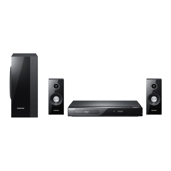
2.1CH Blu-ray Home Theater System
HT-C5200
Refer to the service manual in the GSPN (see the rear cover) for the more information.
2.1CH Blu-ray
Home Theater System
Model Name : HT-C5200
Model Code : HT-C5200/EDC
Speaker
PS-C5200
Front
PS-FC5200
Subwoofer
PS-WC5200
Manual
1. Precaution
2. Product Specification
3. Disassembly & Reassembly
4. Troubleshooting
5. Exploded View & Part List
6. PCB Diagram
7. Schematic Diagram
CONTENTS
Advertisement
Table of Contents


Need help?
Do you have a question about the HT-C5200/EDC and is the answer not in the manual?
Questions and answers