Table of Contents
Advertisement
Advertisement
Table of Contents

Related Manuals for Ubiquiti UBNT-US-8-150W-US


Summary of Contents for Ubiquiti UBNT-US-8-150W-US
- Page 1 Managed PoE+ Gigabit Switch with SFP Model: US-8-150W...
-
Page 2: Package Contents
Introduction Thank you for purchasing the Ubiquiti Networks® UniFi® Switch. This Quick Start Guide is designed to guide you through the installation and also includes the warranty terms. Package Contents UniFi Switch Power Cord Mount Brackets Bracket Screws (Qty. 2) (M4, Qty. -
Page 3: Network Topology Requirements
Network Topology Requirements • A DHCP-enabled network for the UniFi Switch to obtain an IP address (connected devices will also obtain IP addresses after deployment) • A UniFi Cloud Key or management station running the UniFi Controller software v5 or above (recommended) or v4.8.x (possibly offering reduced feature set), located either on-site and connected to the same Layer 2 network, or off-site in a cloud or NOC... -
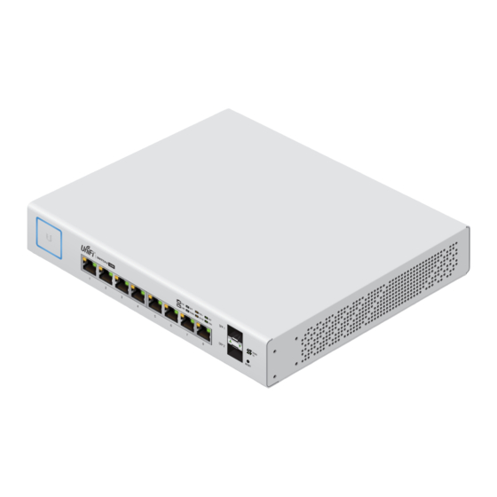
Page 4: Hardware Overview
Hardware Overview Front Panel RJ45 1-8 SFP 1-2 Reset Button Port Description RJ45 ports support 10/100/1000 Ethernet RJ45 1-8 connections and Power over Ethernet (PoE). Hot-swappable SFP ports support 1 Gbps SFP 1-2 connections. This button serves two functions for the UniFi Switch: •... - Page 5 LEDs RJ45 System Link/Speed/Activity Link/Speed/Activity System LED State Status Flashing White Initializing. Steady White Factory defaults, waiting for integration. Device is busy; do not touch or unplug it. Alternating This usually indicates that a process such White/Blue as a firmware upgrade is taking place. Successfully integrated into a network Steady Blue and working properly.
- Page 6 RJ45 LEDs State Status No PoE Amber IEEE 802.3af/802.3at Green 24V Passive No Link Link Established at 10/100 Mbps Amber Link/ Flashing Indicates Activity Speed/ Activity Link Established at 1000 Mbps (1 Gbps) Green Flashing Indicates Activity SFP LEDs State Status No Link Link/ Speed/ Link Established at 1 Gbps...
-
Page 7: Side Panels
Side Panels Ventilation Holes WARNING: FAILURE TO PROVIDE PROPER VENTILATION MAY CAUSE FIRE HAZARD. KEEP AT LEAST 20 MM OF CLEARANCE NEXT TO THE VENTILATION HOLES FOR ADEQUATE AIRFLOW. WARNING: The US-8-150W must not be stacked. Do not place it on top of another switch. Do not place anything on top of the US-8-150W. -
Page 8: Hardware Installation
Hardware Installation WARNING: To reduce the risk of fire or electric shock, do not expose the switch to rain or moisture. Shelf Mounting 1. Position the two Mount Brackets as shown below, and attach the brackets using the eight Bracket Screws. 2. -
Page 9: Wall Mounting
Wall Mounting 1. Position the two Mount Brackets as shown below, and attach the brackets using the eight Bracket Screws. 2. Attach the UniFi Switch to the wall using the four Screw Anchors and four Mounting Screws. -
Page 10: Connecting Power
Connecting Power 1. Connect the Power Cord to the power port on the back of the UniFi Switch. 2. Plug the Power Cord into a power outlet. -
Page 11: Connecting Ethernet
Connecting Ethernet 1. Connect an Ethernet cable from your DHCP server or LAN to any port on the UniFi Switch. 2. Connect your computer or host system and other devices to the other ports on the UniFi Switch. - Page 12 Using SFP Ports To use an SFP port: 1. Remove the dust plug covering the SFP port. 2. Insert a compatible fiber SFP module into the SFP port. 3. Connect the fiber optic cable to the fiber SFP module. For information about compatible fiber SFP modules, visit: community.ubnt.com/unifi...
-
Page 13: Software Installation
Software Installation Download and install the latest version of the UniFi Controller software at downloads.ubnt.com/unifi and follow the on-screen instructions. Note: If you already have UniFi Controller v4.8.x or above installed, skip to the section, Adopting the UniFi Switch. After you have installed the software and run the UniFi Installation Wizard, a login screen will appear for the UniFi Controller management interface. - Page 14 Adopting the UniFi Switch 1. From the UniFi Controller dashboard, click Devices in the left menu bar. 2. On the Devices screen, locate the UniFi Switch in the list of devices under the Model column. To adopt the UniFi Switch, click Adopt. 3.
-
Page 15: Configuring Poe Settings
Configuring PoE Settings By default, PoE settings for ports 1-8 are set to auto-sensing PoE+. PoE will automatically be activated on the port when an 802.3af/at device is connected. For 24V passive PoE, PoE must be manually activated. WARNING: Before manually activating 24V passive PoE, ensure that the connected device supports 24V passive PoE. - Page 16 3. Click Actions for the port you want to configure. 4. Select the appropriate mode: Off, 24V Passive, or PoE+ from the PoE setting. Then click Apply. For more information, refer to the User Guide on the website: documentation.ubnt.com/unifi...
-
Page 17: Specifications
Specifications UniFi Switch US-8-150W Dimensions 204 x 43 x 235 mm (8.03 x 1.69 x 9.25") Weight 1.65 kg (3.64 lb) With Mount Brackets 1.73 kg (3.81 lb) Interfaces Networking (8) 10/100/1000 Mbps RJ45 Ports (2) 1 Gbps SFP Ports Ethernet In-Band Management Power Method... -
Page 18: Safety Notices
Safety Notices Read, follow, and keep these instructions. Heed all warnings. Only use attachments/accessories specified by the manufacturer. WARNING: Failure to provide proper ventilation may cause fire hazard. Keep at least 20mm of clearance next to the ventilation holes for adequate airflow. WARNING: To reduce the risk of fire or electric shock, do not expose this product to rain or moisture. -
Page 19: Limited Warranty
Ubiquiti MAC label, or is missing any other original Ubiquiti label(s); or (VII) has not been received by Ubiquiti within 30 days of issuance of the RMA. In addition, the above warranty shall apply only if: the product has been properly installed and used at all times in accordance, and in all material respects, with the applicable Product documentation;... - Page 20 No Products will be accepted for replacement or repair without obtaining a Return Materials Authorization (RMA) number from UBIQUITI NETWORKS during the warranty period, and the Products being received at UBIQUITI NETWORKS’ facility freight prepaid in accordance with the RMA process of UBIQUITI NETWORKS.
-
Page 21: Limitation Of Liability
Limitation of Liability EXCEPT TO THE EXTENT PROHIBITED BY LOCAL LAW, IN NO EVENT WILL UBIQUITI OR ITS SUBSIDIARIES, AFFILIATES OR SUPPLIERS BE LIABLE FOR DIRECT, SPECIAL, INCIDENTAL, CONSEQUENTIAL OR OTHER DAMAGES (INCLUDING LOST PROFIT, LOST DATA, OR DOWNTIME COSTS), ARISING... -
Page 22: Industry Canada
Compliance Changes or modifications not expressly approved by the party responsible for compliance could void the user’s authority to operate the equipment. This device complies with Part 15 of the FCC Rules. Operation is subject to the following two conditions: This device may not cause harmful interference, and This device must accept any interference received, including interference that may cause undesired operation. -
Page 23: Australia And New Zealand
Australia and New Zealand Warning: This is a Class A product. In a domestic environment this product may cause radio interference in which case the user may be required to take adequate measures. CE Marking CE marking on this product represents the product is in compliance with all directives that are applicable to it. - Page 24 RoHS/WEEE Compliance Statement English European Directive 2012/19/EU requires that the equipment bearing this symbol on the product and/or its packaging must not be disposed of with unsorted municipal waste. The symbol indicates that this product should be disposed of separately from regular household waste streams.
- Page 25 Español La Directiva 2012/19/UE exige que los equipos que lleven este símbolo en el propio aparato y/o en su embalaje no deben eliminarse junto con otros residuos urbanos no seleccionados. El símbolo indica que el producto en cuestión debe separarse de los residuos domésticos convencionales con vistas a su eliminación.
-
Page 26: Declaration Of Conformity
Ezennel UBIQUITI NETWORKS kijelenti, hogy ez a UBIQUITI NETWORKS készülék megfelel az alapvető követelményeknek és más [Hungarian] vonatkozó 2014/30/EU, 2014/35/EU irányelvek rendelkezéseit. Íslenska Hér, UBIQUITI NETWORKS, því yfir að þetta UBIQUITI NETWORKS tæki er í samræmi við grunnkröfur og önnur viðeigandi ákvæði tilskipana [Icelandic] 2014/30/ESB, 2014/35/ESB. Italiano Con la presente, UBIQUITI NETWORKS, dichiara che questo dispositivo UBIQUITI NETWORKS, è... - Page 27 [Slovak] a ďalšími relevantnými ustanoveniami smernice 2014/30/EÚ, 2014/35/EÚ. Español Por medio de la presente UBIQUITI NETWORKS declara que este dispositivo UBIQUITI NETWORKS, cumple con los requisitos [Spanish] esenciales y cualesquiera otras disposiciones aplicables o exigibles de las Directivas 2014/30/UE, 2014/35/UE.
- Page 28 . u b n t . c o m ©2015-2016 Ubiquiti Networks, Inc. All rights reserved. Ubiquiti, Ubiquiti Networks, the Ubiquiti U logo, the Ubiquiti beam logo, and UniFi are trademarks or registered trademarks of Ubiquiti Networks, Inc. in the United States and in other countries.
Need help?
Do you have a question about the UBNT-US-8-150W-US and is the answer not in the manual?
Questions and answers