Ubiquiti unifi switch 8 Quick Start Manual
8-port poe-powered gigabit switch with poe passthrough
Hide thumbs
Also See for unifi switch 8:
- Quick start manual (15 pages) ,
- Quick start manual (13 pages) ,
- Quick start manual (29 pages)
Table of Contents
Advertisement
Advertisement
Table of Contents

Subscribe to Our Youtube Channel
Related Manuals for Ubiquiti unifi switch 8


Summary of Contents for Ubiquiti unifi switch 8
- Page 1 8-Port PoE-Powered Gigabit Switch with PoE Passthrough Model: US-8...
-
Page 2: Package Contents
Introduction Thank you for purchasing the Ubiquiti Networks® UniFi® 8-Port PoE-Powered Gigabit Switch with PoE Passthrough. This Quick Start Guide is designed to guide you through the installation and also includes the warranty terms. Package Contents UniFi Switch Mounting Screws Screw Anchors (Qty. -
Page 3: Network Topology Requirements
Network Topology Requirements • A DHCP-enabled network for the UniFi Switch to obtain an IP address (connected devices will also obtain IP addresses after deployment) • A UniFi Cloud Key or management station running the UniFi Controller software v5.3 (or newer), located either on-site and connected to the same Layer 2 network, or off-site in a cloud or NOC UniFi Cloud Key... -
Page 4: Hardware Overview
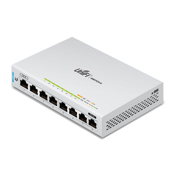
Hardware Overview Front Panel Ports 1-8 PoE In PoE Out Port Description Ports 1-8 RJ45 ports support 10/100/1000 Ethernet connections. PoE In Supports 802.3af/at or 48V Passive PoE to (Port 1) power the switch and can provide 48V (2-pair) PoE passthrough to port 8. PoE Out PoE output is Off by default. -
Page 5: Back Panel
Back Panel Reset Ground DC In Button Port Description Ground Ancillary grounding point for enhanced ESD protection. DC In To power the switch by DC input, connect a 48V power adapter to the 48VDC port. Reset This button serves two functions for the UniFi Button Switch: Restart... - Page 6 LEDs System System LED State Status Flashing White Initializing. Steady White Factory defaults, waiting for integration. Alternating Device is busy; do not touch or unplug it. White/Blue This usually indicates that a process such as a firmware upgrade is taking place. Steady Blue Successfully integrated into a network and working properly.
- Page 7 RJ45 LEDs Link DOWN 10/100 1000 Link/Speed/Activity State Status PoE Disabled Amber 48V Passive PoE No Link Link Established at 10/100 Mbps Link/ Amber Speed/ Flashing Indicates Activity Activity Link Established at 1 Gbps Green Flashing Indicates Activity...
-
Page 8: Side Panels
Side Panels Ventilation Holes WARNING: FAILURE TO PROVIDE PROPER VENTILATION MAY CAUSE FIRE HAZARD. KEEP AT LEAST 20 MM OF CLEARANCE NEXT TO THE VENTILATION HOLES FOR ADEQUATE AIRFLOW. WARNING: The US-8 must not be stacked. Do not place it on top of another switch. -
Page 9: Hardware Installation
Hardware Installation The UniFi Switch can be mounted on a vertical surface or placed on a desktop. Follow the Wall Mounting instructions to mount the switch using the included screws and anchors. WARNING: To reduce the risk of fire or electric shock, do not expose the switch to rain or moisture. - Page 10 4. Mount the UniFi Switch by inserting the screw heads into the mounting slots on the bottom of the switch. Then slide the switch down to lock it in place.
-
Page 11: Connecting Power
Grounding (Recommended) The UniFi Switch is grounded through the Power Adapter. When powering the switch with PoE, ground the device by connecting the ancillary ground. 1. Loosen the ground screw and secure a ground wire (not included) to the grounding point. 2. - Page 12 Power by DC Input 1. Connect the Power Adapter to the 48VDC port on the back of the UniFi Switch. 2. Connect the Power Cord to the Power Adapter. Plug the Power Cord into a power outlet.
-
Page 13: Connecting Ethernet
Connecting Ethernet 1. Connect an Ethernet cable from your DHCP server or LAN to any port 1 to 7. 2. Connect your PoE device to port 8. WARNING: Before enabling PoE passthrough in the UniFi Controller, ensure that the connected PoE device supports the PoE power (48V). -
Page 14: Software Installation
Software Installation Download and install the latest version of the UniFi Controller software at downloads.ubnt.com/unifi and follow the on-screen instructions. Note: If you already have UniFi Controller v5.3.x or newer installed, skip to the section, Adopting the UniFi Switch. After you have installed the software and run the UniFi Installation Wizard, a login screen will appear for the UniFi Controller management interface. - Page 15 Adopting the UniFi Switch 1. From the UniFi Controller dashboard, click Devices in the left menu bar. 2. On the Devices screen, locate the UniFi Switch in the list of devices under the Model column. To adopt the UniFi Switch, click Adopt. 3.
-
Page 16: Specifications
Specifications US-8 Dimensions 148 x 99.5 x 30.7 mm (5.83 x 3.92 x 1.21") Weight 432 g (15.24 oz) Networking Interfaces (8) 10/100/1000 Mbps RJ45 Ports PoE In (Port 1) PoE Mode 1: 802.3af/at (Pins +1, 2; -3, 6) PoE Mode 2: Passive 48V (Pins +4, 5;... - Page 17 US-8 Code Storage 32 MB NOR Flash Line Rate 8 Gbps, Non-Blocking LEDs System Status RJ45 Data Ports PoE; Link/Speed/Activity ESD/EMP Protection ± 24kV Air, ± 24kV Contact Operating Temperature -5 to 45° C (23 to 113° F) Operating Humidity 5 to 95% Noncondensing Certifications CE, FCC, IC...
-
Page 18: Safety Notices
Safety Notices Read, follow, and keep these instructions. Heed all warnings. Only use attachments/accessories specified by the manufacturer. WARNING: Failure to provide proper ventilation may cause fire hazard. Keep at least 20 mm of clearance next to the ventilation holes for adequate airflow. WARNING: To reduce the risk of fire or electric shock, do not expose this product to rain or moisture. -
Page 19: Electrical Safety Information
Electrical Safety Information Compliance is required with respect to voltage, frequency, and current requirements indicated on the manufacturer’s label. Connection to a different power source than those specified may result in improper operation, damage to the equipment or pose a fire hazard if the limitations are not followed. -
Page 20: Limited Warranty
Ubiquiti MAC label, or is missing any other original Ubiquiti label(s); or (VII) has not been received by Ubiquiti within 30 days of issuance of the RMA. In addition, the above warranty shall apply only if: the product has been properly installed and used at all times in accordance, and in all material respects, with the applicable Product documentation;... -
Page 21: Limitation Of Liability
SUBJECT TO LIMITATIONS, INTERRUPTIONS, DELAYS, CANCELLATIONS AND OTHER PROBLEMS INHERENT IN THE USE OF COMMUNICATIONS FACILITIES. UBIQUITI NETWORKS, ITS AFFILIATES AND ITS AND THEIR THIRD PARTY PROVIDERS ARE NOT RESPONSIBLE FOR ANY INTERRUPTIONS, DELAYS, CANCELLATIONS, DELIVERY FAILURES, DATA LOSS, CONTENT CORRUPTION, PACKET LOSS, OR OTHER DAMAGE RESULTING FROM ANY OF THE FOREGOING. - Page 22 Note Some countries, states and provinces do not allow exclusions of implied warranties or conditions, so the above exclusion may not apply to you. You may have other rights that vary from country to country, state to state, or province to province. Some countries, states and provinces do not allow the exclusion or limitation of liability for incidental or consequential damages, so the above limitation may not apply to you.
-
Page 23: Industry Canada
Industry Canada CAN ICES-3(A)/NMB-3(A) This Class A digital apparatus complies with Canadian CAN ICES-3(A). CAN ICES-3(A)/NMB-3(A) Cet appareil numérique de la classe A est conforme à la norme NMB-3(A) Canada. Australia and New Zealand Warning: This is a Class A product. In a domestic environment this product may cause radio interference in which case the user may be required to take adequate measures. - Page 24 RoHS/WEEE Compliance Statement English European Directive 2012/19/EU requires that the equipment bearing this symbol on the product and/or its packaging must not be disposed of with unsorted municipal waste. The symbol indicates that this product should be disposed of separately from regular household waste streams.
- Page 25 Español La Directiva 2012/19/UE exige que los equipos que lleven este símbolo en el propio aparato y/o en su embalaje no deben eliminarse junto con otros residuos urbanos no seleccionados. El símbolo indica que el producto en cuestión debe separarse de los residuos domésticos convencionales con vistas a su eliminación.
-
Page 26: Declaration Of Conformity
Ezennel UBIQUITI NETWORKS kijelenti, hogy ez a UBIQUITI NETWORKS készülék megfelel az alapvető követelményeknek és más [Hungarian] vonatkozó 2014/30/EU, 2014/35/EU irányelvek rendelkezéseit. Íslenska Hér, UBIQUITI NETWORKS, því yfir að þetta UBIQUITI NETWORKS tæki er í samræmi við grunnkröfur og önnur viðeigandi ákvæði tilskipana [Icelandic] 2014/30/ESB, 2014/35/ESB. Italiano Con la presente, UBIQUITI NETWORKS, dichiara che questo dispositivo UBIQUITI NETWORKS, è... - Page 27 [Slovak] a ďalšími relevantnými ustanoveniami smernice 2014/30/EÚ, 2014/35/EÚ. Español Por medio de la presente UBIQUITI NETWORKS declara que este dispositivo UBIQUITI NETWORKS, cumple con los requisitos [Spanish] esenciales y cualesquiera otras disposiciones aplicables o exigibles de las Directivas 2014/30/UE, 2014/35/UE.
- Page 28 . u b n t . c o m ©2016-2017 Ubiquiti Networks, Inc. All rights reserved. Ubiquiti, Ubiquiti Networks, the Ubiquiti U logo, the Ubiquiti beam logo, and UniFi are trademarks or registered trademarks of Ubiquiti Networks, Inc.
Need help?
Do you have a question about the unifi switch 8 and is the answer not in the manual?
Questions and answers