
Related Manuals for Ubiquiti USW-Flex


Summary of Contents for Ubiquiti USW-Flex
- Page 1 Indoor/Outdoor 5-Port PoE Gigabit Switch with 802.3bt Input Power Support Model: USW-Flex...
-
Page 2: Package Contents
Package Contents UniFi Switch Flex Wall Mount Pole Mount Port Cover Mounting Screws Screw Anchors Zip Ties (Qty. 2) (Qty. 2) (Qty. 2) System Requirements • Linux, Mac OS X, or Microsoft Windows 7/8/10 • Java Runtime Environment 1.8 or above recommended •... -
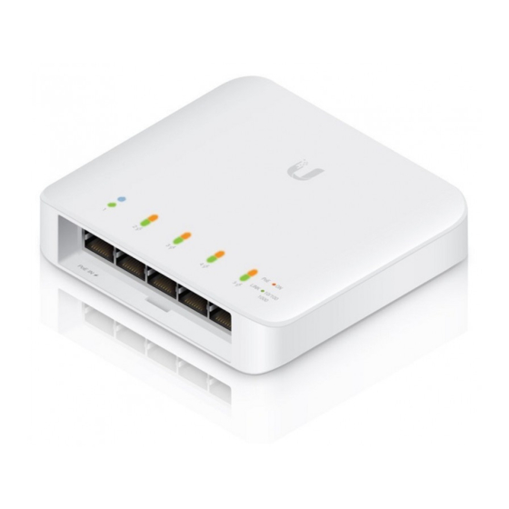
Page 3: Hardware Overview
Hardware Overview Front Panel Port Description Ports 1-5 RJ45 ports support 10/100/1000 Mbps Ethernet connections. PoE In Supports 802.3af/at/bt (Port 1) Top Panel... - Page 4 LEDs System State Status Steady White Factory defaults, awaiting adoption. Flashing White Bootup in process. Steady Blue Successfully adopted. Flashing Blue Firmware upgrade in process. RJ-45 LEDs State Status No PoE Amber Powered on, IEEE 802.3af No Link Link/ Speed/ Link established at 10/100/1000 Mbps Green Activity...
-
Page 5: Hardware Installation
Hardware Installation The UniFi Switch can be placed on a flat surface or mounted on a wall or pole. Wall Mounting 1. Use the Wall Mount as a template to mark two holes on the installation surface. 40 mm 2. Use a 6mm drill bit to predrill the two holes. - Page 6 3. Insert the screw anchors into the predrilled holes and secure the Wall Mount using the Mounting Screws. 4. Mount the switch to the wall by pressing it over the Wall Mount and sliding it down until it locks into place.
-
Page 7: Magnetic Mounting
Magnetic Mounting 1. Slide the Wall Mount into the rear panel of the switch until it snaps into place. 2. Place or hang the switch on a magnetic surface. -
Page 8: Pole Mounting
Pole Mounting 1. Slide the two Plastic Zip Ties through the notches in the Pole Mount and fasten to the pole. 2. Press the switch over the Pole Mount and slide it down until it locks into place. NOTE: For outdoor installations, please install the Port Cover prior to connecting your Ethernet cables. -
Page 9: Powering The Switch
Powering the Switch Connect an Ethernet cable from an 802.3af/at/bt switch or PoE adapter to the PoE In port (Port 1) on the switch. Connecting Ethernet 1. Connect an Ethernet cable from your DHCP server or LAN device to any port 2 through 5. NOTE: For outdoor installations, please install the Port Cover prior to connecting your Ethernet cables. -
Page 10: Outdoor Installation
Outdoor Installation 1. Attach the bottom half of the Port Cover to the switch and snap it into place. 2. Connect an Ethernet cable from an 802.3af/at/bt switch or PoE adapter to the PoE In port (Port 1) on the switch and a LAN cable to any port 2 through 5. - Page 11 Disconnect Ethernet Cable(s) 1. Remove the Port Cover from the USW-Flex. 2. Disconnect the Ethernet cable(s) from the USW-Flex. 3. Separate the top half of the Port Cover from the bottom half. 4. Slide the Ethernet cables out through the opening of...
-
Page 12: Software Installation
Software Installation Download and install the latest version of the UniFi Controller software at ui.com/download/unifi and follow the on-screen instructions. Note: If you already have UniFi Controller v5.10.x or newer installed, skip to Adopting the UniFi Switch. After you have installed the software and run the UniFi Installation Wizard, a login screen will appear for the UniFi Controller management interface. - Page 13 Adopting the UniFi Switch 1. From the UniFi Controller dashboard, click Devices in the left menu bar. 2. On the Devices screen, locate the UniFi Switch in the list of devices under the Model column. To adopt the UniFi Switch, click Adopt. 3.
- Page 14 Enabling PoE Injector Mode 1. In UniFi Controller, click the Devices icon and select UniFi Switch Flex 5 POE from the list. 2. Click the Config icon in the Properties window.
- Page 15 The option to select PoE Injector will only appear if the switch is actually powered by a PoE injector. 4. Click Confirm if the USW-Flex is powered by a PoE Adapter with a power rating of 50V/60W or better. Otherwise, click Cancel and replace the PoE Adapter with one that does have a power rating of 50V/60W or better.
-
Page 16: Specifications
Specifications USW-Flex Dimensions 122.5 x 107.1 x 28.0 mm (4.82 x 4.22 x 1.10") Weight 230 g (8.11 oz) Networking Interfaces (5) 10/100/1000 Mbps RJ45 Ports Management Interface Ethernet In-Band Power Method (Port 1) PoE Mode 1 802.3af/at (Pins 1, 2+; 3, 6-)1 PoE Mode 2 802.3bt (Pins 1, 2+;... -
Page 17: Safety Notices
Safety Notices Read, follow, and keep these instructions. Heed all warnings. Only use attachments/accessories specified by the manufacturer. WARNING: Failure to provide proper ventilation may cause fire hazard. Keep at least 20 mm of clearance next to the ventilation holes for adequate airflow. WARNING: To reduce the risk of fire or electric shock, do not expose this product to rain or moisture. -
Page 18: Australia And New Zealand
Compliance Changes or modifications not expressly approved by the party responsible for compliance could void the user’s authority to operate the equipment. This device complies with part 15 of the FCC Rules. Operation is subject to the following two conditions: (1) This device may not cause harmful interference, and (2) this device must accept any interference received, including interference that may cause undesired operation. -
Page 19: Rohs/Weee Compliance Statement
CE Marking CE marking on this product represents the product is in compliance with all directives that are applicable to it. RoHS/WEEE Compliance Statement English European Directive 2012/19/EU requires that the equipment bearing this symbol on the product and/or its packaging must not be disposed of with unsorted municipal waste. - Page 20 Español La Directiva 2012/19/UE exige que los equipos que lleven este símbolo en el propio aparato y/o en su embalaje no deben eliminarse junto con otros residuos urbanos no seleccionados. El símbolo indica que el producto en cuestión debe separarse de los residuos domésticos convencionales con vistas a su eliminación.
-
Page 21: Declaration Of Conformity
Az EU-megfelelőségi nyilatkozat teljes szövege elérhető a következő internetes címen: ui.com/compliance Íslenska [Icelandic] Hér, UBIQUITI, því yfir að þetta USW-Flex tæki er í samræmi við grunnkröfur og önnur viðeigandi ákvæði tilskipana 2014/30/ESB, 2014/35/ESB. Fullur texti ESB samræmisyfirlýsing er að finna á eftirfarandi netfangi: ui.com/compliance... - Page 22 Id-dikjarazzjoni tal-konformità tista’ tiġi kkonsultata minn ui.com/compliance Norsk [Norwegian] Herved UBIQUITI, erklærer at denne USW-Flex enheten, er i samsvar med de grunnleggende kravene og andre relevante bestemmelser i direktivene 2014/30/EU, 2014/35/EU. Den fulle teksten til EU-samsvarserklæringen er tilgjengelig på følgende internettadresse: ui.com/compliance...
-
Page 23: Online Resources
685 Third Avenue, 27th Floor New York, NY 10017 ©2019 Ubiquiti Inc. All rights reserved. Ubiquiti, the Ubiquiti U logo, the Ubiquiti beam logo, TOUGHCable, and UniFi are trademarks or registered trademarks of Ubiquiti Networks, Inc. in the United States and in other countries.
Need help?
Do you have a question about the USW-Flex and is the answer not in the manual?
Questions and answers