Sign In
Upload
Download
Table of Contents
Contents
Add to my manuals
Delete from my manuals
Share
URL of this page:
HTML Link:
Bookmark this page
Add
Manual will be automatically added to "My Manuals"
Print this page
×
Bookmark added
×
Added to my manuals
Manuals
Brands
Fujitsu Manuals
Air Conditioner
AUTG09LVLB
Design & technical manual
Fujitsu AUTG09LVLB Design & Technical Manual
Cassette type
Hide thumbs
1
2
Table Of Contents
3
4
5
6
7
8
9
10
11
12
13
14
15
16
17
18
19
20
21
22
23
24
25
26
27
28
29
30
31
32
33
34
35
36
37
38
39
40
41
42
43
44
45
46
47
48
49
50
51
52
53
54
55
56
57
58
page
of
58
Go
/
58
Contents
Table of Contents
Bookmarks
Table of Contents
Table of Contents
Part 1. INDOOR UNIT
Product Features
Model Lineup
Features
Remote Controller
Wireless Remote Controller
Specifications
Models: AUTG09LVLB and AUTG12LVLB
Dimensions
Models: AUTG09LVLB and AUTG12LVLB
Wiring Diagram
Models: AUTG09LVLB and AUTG12LVLB
Capacity Table
Cooling Capacity
Heating Capacity
Fan Performance
Air Velocity Distributions
Airflow
Operation Noise (Sound Pressure)
Noise Level Curve
Sound Level Check Point
Safety Devices
External Input and Output
10-1.External Input
10-2.External Output
Function Settings
11-1.Function Settings by Using Remote Controller
Accessories
12-1.Models: AUTG09LVLB and AUTG12LVLB
12-2.Cassette Grille Accessories
Optional Parts
13-1.Controllers
13-2.Cassette Grille
13-3.Others
Part 2. OUTDOOR UNIT
Specifications
Models: AOTG09LBCB and AOTG12LBCB
Dimensions
Models: AOTG09LBCB and AOTG12LBCB
Installation Space Requirement
Refrigerant Circuit
Models: AOTG09LBCB and AOTG12LBCB
Wiring Diagrams
Models: AOTG09LBCB and AOTG12LBCB
Capacity Compensation Rate for Pipe Length and Height Difference
Models: AOTG09LBCB and AOTG12LBCB
Additional Charge Calculation
Models: AOTG09LBCB and AOTG12LBCB
Airflow
Model: AOTG09LBCB
Model: AOTG12LBCB
Operation Noise (Sound Pressure)
Noise Level Curve
Sound Level Check Point
Electrical Characteristics
Safety Devices
Accessories
Advertisement
Quick Links
Download this manual
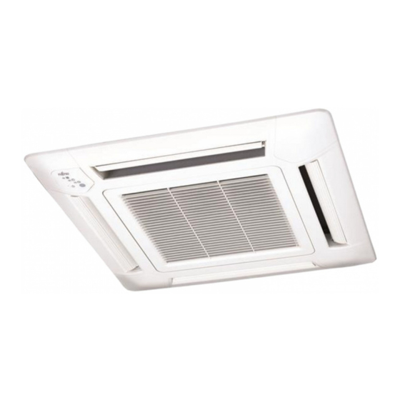
AIR CONDITIONER
Cassette type
DESIGN & TECHNICAL MANUAL
INDOOR
OUTDOOR
AUTG09LVLB
AUTG12LVLB
AOTG09LBCB
AOTG12LBCB
DR_AU003EF_01
2016.01.28
Table of
Contents
Previous
Page
Next
Page
1
2
3
4
5
Advertisement
Table of Contents
Need help?
Do you have a question about the AUTG09LVLB and is the answer not in the manual?
Ask a question
Questions and answers
Related Manuals for Fujitsu AUTG09LVLB
Air Conditioner Fujitsu AUT Series Operating Manual
Air conditioner cassette type (20 pages)
Air Conditioner Fujitsu AUT Series Operating Manual
Air conditioner cassette type (16 pages)
Air Conditioner Fujitsu AUT Series Operating Manual
Air conditioner cassette type (16 pages)
Air Conditioner Fujitsu Inverter AUTG54LR Operating Manual
Cassette type indoor unit (20 pages)
Air Conditioner Fujitsu Inverter 9374379453 Operating Manual
Air conditioner compact cassette type heat & cool model (reverse cycle) (20 pages)
Air Conditioner Fujitsu AUT36A Operating Manual
Air conditioners cassette type (19 pages)
Air Conditioner Fujitsu AUT12 Operating Manual
(20 pages)
Air Conditioner Fujitsu autg30krla Operating Manual
Cassette type (12 pages)
Air Conditioner Fujitsu AUT36ALA3W Service Manual
Cassette type 50 hz (34 pages)
Air Conditioner Fujitsu AUG54AGB3W Service Manual
(31 pages)
Air Conditioner Fujitsu AUTG12LVLB Design & Technical Manual
Cassette type (58 pages)
Air Conditioner Fujitsu AUTH09KVLA Operation Manual
(12 pages)
Air Conditioner Fujitsu AIRSTAGE AUTH24KVLA Operation Manual
(8 pages)
Air Conditioner Fujitsu AUTA30LBLU Design & Technical Manual
(55 pages)
Air Conditioner Fujitsu AUU7RLF Design & Technical Manual
Multi: 5 rooms type (245 pages)
Air Conditioner Fujitsu Mini-Split Manual
Mini-split air conditioners and heat pumps (48 pages)
This manual is also suitable for:
Autg12lvlb
Aotg09lbcb
Aotg12lbcb
Table of Contents
Print
Rename the bookmark
Delete bookmark?
Delete from my manuals?
Login
Sign In
OR
Sign in with Facebook
Sign in with Google
Upload manual
Upload from disk
Upload from URL


Need help?
Do you have a question about the AUTG09LVLB and is the answer not in the manual?
Questions and answers