Etnyre Black-Topper Operation Maintenance Safety
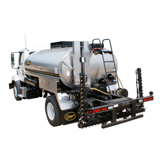
Asphalt distributor with touch screen controls
Hide thumbs
Also See for Black-Topper:
- Operation, maintenance and safety manual (71 pages) ,
- Manual supplement (38 pages) ,
- Manual (20 pages)
Table of Contents
Advertisement
Quick Links
M-103-22
With Touch Screen Controls
Starting with Serial Number S9000
Black-Topper
®
R R
Asphalt Distributor
with Touch Screen Controls
Standard and Variable Width Spray Bar
Operation - Maintenance - Safety
E.D. ETNYRE & CO. - 1333 S. Daysville Road - Oregon, Illinois 61061
Phone: 815-732-2116 or 800-995-2116 – Fax: 800-521-1107 – www.etnyre.com
Parts/Service: 888-586-1899 – CustomerService@etnyre.com
Advertisement
Table of Contents

Related Manuals for Etnyre Black-Topper


Summary of Contents for Etnyre Black-Topper
- Page 1 Touch Screen Controls Standard and Variable Width Spray Bar Operation - Maintenance - Safety E.D. ETNYRE & CO. - 1333 S. Daysville Road - Oregon, Illinois 61061 Phone: 815-732-2116 or 800-995-2116 – Fax: 800-521-1107 – www.etnyre.com Parts/Service: 888-586-1899 – CustomerService@etnyre.com...
-
Page 2: Warranty
M-103-22 Black-Topper Operation, Maintenance and Safety Manual BLACK-TOPPER Distributor Standard Spraybar or Variable Width Bar with Touch Screen Controls Starting with Serial Number S9000... - Page 3 © Copyright 2021 E.D. Etnyre & Co. All brand names, trademarks and registered trademarks are the property of their respective owners. Information contained within this document is subject to change without notice. All rights reserved.
-
Page 4: Table Of Contents
Valve Abbreviations - Variable WidthBar Computer IOs ...........32 APPENDIX C - ......95 USB application Update Left Variable Width Spray Bar ......32 APPENDIX D - ....96 Default GPM & LPM Chart Right Variable Width Spray Bar ......32 Etnyre Spraybar Nozzles ........97 Serial Number Plate Location......98... - Page 5 Figure 88 - Valve Positions for Transfer ......71 Figure 38 - Help Screen ..........35 Figure 89 - Ignition & Out Fire Control System....73 Figure 39 - Black-Topper Computator ......35 Figure 90 - Gun Assembly ..........78 Figure 40 - Information Screen ........36 Figure 91 - Electrode Setting ...........
-
Page 6: Warning And Instruction Plates
Warning and Instruction Plates For operator safety and possible liability protection, all Safety and Instruction Plates should remain in place and be legible Should a plate be removed, lost, or become illegible, reorder and replace immediately If plates become difficult to read because of material coating the surface, clean with solvent 6705038 Gauge-Tank, LED Figure 1. - Page 7 • It is believed the chemistry of the emulsion - specifically the residual fumes promote the corrosion • Etnyre Distributors are compatible with Cationic Emulsions provided that certain precautions are taken. • Prior to placing a distributor in to service with Cationic Emulsion, it should be loaded with an AC or MC type material to develop a protective coating.
-
Page 8: General Safety Instructions
GENERAL SAFETY INSTRUCTIONS The operation of a bituminous distributor normally requires handling of liquid products at elevated temperature. Also, these liquids may be of a volatile nature. A heating system is supplied to raise or maintain the product temperature, and these systems use highly combustible fuels. As with any type of construction equipment, there are certain hazards associated with careless or improper operation. -
Page 9: Fluoroelastomer Handling
WARNING WARNING A fully charged dry chemical type fire To prevent an explosion or fire hazard: extinguisher must be within easy reach • Do not operate the burners when the vehicle is whenever the burners are operating or there is unattended, when the vehicle is in motion, or an open flame near the Distributor. - Page 10 WARNING WARNING Using the Measuring Stick If a flue is not covered by 6” of material, the corre-...
-
Page 11: Foaming
Etnyre dealer, or Etnyre representative. Dow-Corning DC-200 may be used to prevent foaming in Distributors, Transports, and Maintenance Units. The Centennial Distributor is designed to handle a number of different products, such as ACs, cutbacks Mix the contents of one can (16 oz.) with one (1) gallon... -
Page 12: Introduction
This manual is provided as a tool to aid personnel in the operation of the Etnyre Black-Topper® Distributor in a safe and efficient manner. As with any type of construction equipment, there are certain hazards associated with improper or careless operation. -
Page 13: Component Location And Identification
Manhole & Platform LED Tank Gauge Exhaust Stacks Exhaust Stack Dampers Ladder Sample Valve Hand Burners Spray Air Oiler Hydraulic Oil Filters (in right side (Location depends per unit) tool box) Hydraulic Oil Tank Suction Valve (Location depends per unit) Strainer/Valve Box Thermometer Well Asphalt Pump... -
Page 14: Figure 6. Spray Bar Component Identification
Standard Spray Bar Components Right Wing Section Breakaway with Spray Valves Swivel Joint Flip Lever Spray Valve Spray Bar Feed Tubes Nozzle 8' Center Section with Valves and Nozzles Spray Valve Nozzle Left Wing Section Spray Valve Control Linkage and Air Cylinder Figure 6. -
Page 15: Cab Touch Screen Control Panel
CAB TOUCH SCREEN CONTROL PANEL 12g 12i 12f 12h 12j 12l 12m Figure 8 - Cab Control Panel Components 2. MASTER SPRAY Switch 1. One Foot Switches (Bar Module) Turning this switch to ON opens all activated spray The foot-switch LED module indicates status of valves when BAR CIRCULATE or SUCK BACK is each set of three nozzles on the spray bar. - Page 16 4. POWER Switch 10. Right Taper Both the POWER switch in the cab and the EMER- If the Taper Switch paid option is activated, the right GENCY STOP switch in the rear panel must be ON thumbwheel will move the right taper position in ei- for the control system to be ON.
-
Page 17: Rear Touch Screen Control Panel
REAR TOUCH SCREEN CONTROL PANEL 6h 6j 6g 6i Figure 9 - Rear Control Panel Components 1. WING FOLD Switches 4. Left Bar (Variable Width Bar only) Spray bars have fixed center sections and fold- For variable bar units, the left bar thumbwheel will ing wings on both sides. -
Page 18: Preparing For Operation
PREPARING FOR OPERATION... -
Page 19: Settings
Before operating your Distributor, navigate to the Settings page by tapping the gear icon in the Header. Figure 10 - Gear Icon Eight (8) selections are available in Settings and will be explained throughout this manual. Factory is only accessible by an Etnyre service technician and will be ignored. 1. Setup (Pages 19–27) NOTICE 2. -
Page 20: Setup
SETUP SETUP Page 1 Twelve (12) parameters are adjustable in Page 1 of the Setup screen. Tapping the parameter name it its header will show a pop-up window describing that parameter. Exit by tapping anywhere on the pop-up window or the “X”. Figure 13 - Page 1 of Setup Screen Figure 14 - Pump Threshold Description •... -
Page 21: Figure 15 - Reset Defaults Button
Circulation Factor • Sets the target pump flow rate in Bar Circ mode based on the Spray Width and Application Rate. 50% is recommended and half the pump rate required when traveling at 300 FPM while spraying. o Default: 50% •... -
Page 22: Calibrations
Five (5) Setup memories are saved in the computer and can be cycled through with the arrow keys. The com- puter will hold its last memory after a power cycle. When one of the setup parameters changes, Save/Reset buttons will pop up on the Memory title box. These will save new parameters into the memory slot, or reset parameters to what is currently saved in memory. -
Page 23: Left Bar, Right Bar Smart Cylinder (Variable Width Bar Only)
Figure 18 - Machine Calibrations Window Left Bar, Right Bar Smart Cylinder (Variable Width Bar Only) Tap the Left Bar/Right Bar Smart Cylinder Calibration buttons to go to their calibration screen. Refer to Figures 18 & 19. To begin, press the green START button, and fully extend the spray bar. The feedback value, given in millivolts [mV], will increase as the spray bar extends. -
Page 24: Pump Edc Threshold
Pump EDC Threshold The EDC Threshold is the current supplied to the hydraulic pump control at which the asphalt pump begins to spin. This threshold is always set at factory. This screen allows the operator to automatically calibrate the Pump Threshold. -
Page 25: Ground Speed Radar Calibration
Ground Speed Radar Calibration The Distributor’s ground speed is calibrated at the factory. The ground speed displayed on screen is dependent on the physical radar’s height and angle to the ground. While stationary, the ground speed may be displayed greater than 0 due to vibrations in the frame. The following process is used to calibrate the radar: Set up and measure a 300-foot course that is dry and clear of obstacles and debris on the ground. -
Page 26: Tank Level Sensor Calibration
Tank Level Sensor Calibration The distributor uses a 360-degree rotary sensor to calculate the tank level. The feedback is measured in millivolts [mV].Press the green START button to show the Calibrate Empty and Calibrate Full buttons. With the hook designed into the tank stick, move the tank level float arm to the bottom or top of the tank, and hold the corresponding calibrate button. -
Page 27: Setup
SETUP SETUP Page 2 Figure 26 - Page 2 of Setup Screen Page 2 of the Setup screen allows the operator to configure the spray bar. The number of wings and length of each wing can be adjusted. This WILL NOT be adjusted unless a new spray bar is installed on the machine. Do not leave a wing length at 0 feet! Spray Marker Valves If there are marker valves on the ends of the spray bar, Spray Marker Valves should be “Equipped.”, or they... -
Page 28: Setup
USB / Computer Update: To update the display or computer program, you will receive specific update files from an Etnyre Service mem- ber and must put them on an 8 GB flash drive formatted FAT32. Press the UPDATE DISPLAY or UPDATE COM- PUTER buttons to go to the update screens. -
Page 29: Display
DISPLAY DISPLAY Display parameters and settings can be viewed and adjusted in this section. Figure 30 - Display Screen Every touchscreen display has a unique Serial Number (SN). The display firmware (FW) and hardware (HW) versions are also shown. Display firmware updates may be done throughout the life of the machine to add new features. -
Page 30: Color Scheme
If the display’s temperature is above 170°F (75° C), maximum display brightness will be reduced to limit over- heating. The Front Display or Rear Display fault will also be active on the faults screen. Figure 31 - Front Display / Rear Display Color Scheme: Color scheme can be adjusted between standard yellow/white and red/green. -
Page 31: Faults
FAULTS FAULTS An asphalt distributor has twenty-two (22) unique faults that may be active at any time. While Fault Control is active, whenever a new fault is active the display will go to this screen and show the new fault. Newly-activated faults will flash their white title font at one-second intervals, for five total seconds, to indicate is new. -
Page 32: Hydraulic Temperature Hot
• Hydraulic Temperature Hot The hydraulic reservoir temperature is at or over 200 °F (93 °C). WARNING Stop immediately and determine the cause of the high temperature. Failure to do so will result in damage to hydraulic components. • Tank Level Sensor The rotary sensor has been calibrated incorrectly or giving unexpected feedback to the computer. -
Page 33: Hydraulic Output Module
• Hydraulic Output Module The hydraulic output module bank is disconnected from the CAN bus, or a fault code is present on at least one of the outputs. • Accessories Output Module The accessory output module bank is disconnected from the CAN bus, or a fault code is present on at least one of the outputs. -
Page 34: Diagnostics
The Next Generation Asphalt Distributor has much improved diagnostics built in to the touchscreen display Please begin all troubleshooting at this screen before contacting the Etnyre service department. Bus load of the CAN network is given. Under normal operation this should be around 25%. A value less than this may indicate a module on the CAN network is not transmitting messages and disconnected from the bus. -
Page 35: Figure 37 - Page 2 Of Diagnostics Screen
If the thumbwheels or joysticks are not centered in the resting position, a calibration should be performed in Setup Page 1 screen. Page 3 Page 3 is for Etnyre Personnel usage only. Diagnostics... -
Page 36: Help
Press the red X button in the header to close the PDF. Figure 38 - Help Screen The Etnyre Pump Rate Black-Topper Computator is now built in to the touchscreen display. Access it by tapping the Computator button. Adjust desired spray bar length, application rate, and ground speed. The resulting pump speed to reach the application rate is shown in Auto Pump. -
Page 37: Information
This page shows an overview of the distributor machine. Figure 40 - Information Screen The Distributor’s Serial Number (SN) is given in the top left corner. Refer to this when contacting an Etnyre Service representative. A key of all paid-for factory options is given in the bottom right. Please refer to Appendix A (Page 93) to relate abbreviations to options The bottom header shows the application versions of the computer and displays. -
Page 38: Lights
Figure 42 - Lights Icon Button Most Etnyre Distributors have standard Beacon, Strobe, and Work lights that can be turned on from the Lights screen. Each control box has an optional dimmable LED strip to be used as a nightlight. The Tank Level LED can be dimmed or turned off. -
Page 39: Operation
Every time the Distributor controls are powered on, the machine begins in the LOAD operation mode and MANUAL pump control. The touchscreen always begins in its home screen. Tapping the Etnyre oval logo icon in the center of the header will always put the display back to its home screen. -
Page 40: Two Speed Motor (If Equipped)
Page 1 In addition to the main controls, Page 1 gives control for the motor speed, burners, Smart Clean (if equipped), optional valve (if equipped) and suck back bar circ valve (if equipped). Two Speed Motor (if equipped): The hydraulic motor that spins the asphalt pump has two speed settings, HIGH and LOW. A benefit of the LOW speed setting is increased torque spinning the asphalt pump and better control at low flow rates. -
Page 41: Burner Control
Burner Control To control the burners, tap Burner Control to show a pop-up. Desired product temperature can be adjusted up or down. This always begins at 95 F when the controls are turned on. The Upper burner and Lower burner can be turned ON or OFF. -
Page 42: Ignition And Out Fire Control
Ignition and Out Fire Control The burner(s) will automatically shutdown if the built in timer is allowed to expire. The timer can be Fuel Oil Burners reset by the operator at anytime through the Timer Reset switch. The air inlet screen on the burner should be During the last 5 minutes of the timer interval kept clean and free of debris in order for efficient the message, BURNER TIMER ENDING, will be... -
Page 43: Tank Valve (If Equipped)
Tank Valve (if equipped): The optional valve control can be used to toggle which tank valve is being used by the Distributor. If equipped, the tank valve can switch between REAR and MID, or REAR and FRONT. This setting is not saved on a power cycle and always begins in REAR. -
Page 44: Taper Switch (Optional)
Taper Switch (Optional): Taper Switch can be HOLD or CLICK and has an adjustable taper rate given in feet per second. If HOLD, holding a taper switch will move the taper position in the direction the switch is held at the given rate. A smaller rate will taper slower, and a larger rate will taper faster. -
Page 45: Spray Totals
Page 3 In addition to the main controls, Page 3 gives control for spray totals. Figure 58 - Operation page 3 screen Spray Totals: Spray Totals displays Product Sprayed, Distance Traveled, and Area Covered. These parameters are totalized while the Distributor is spraying in Bar Circ with the Master Spray Switch on. They can all be hidden by tapping the totals button to the left. -
Page 46: Tank Capacity
Tank Capacity The Black-Topper® Distributor is designed to pump and spray a variety of asphalt product in an efficient and user friendly manner with great accuracy. For a complete description of each of the controls and how to set up the machine, refer to the Setup section of this manual. -
Page 47: Loading Through The Manhole
Loading Through the Manhole Refer to Figure 61. for the following procedures. 1. Park the Distributor in the desired location for To reduce the risk of accidental discharge of as- loading overhead through the manhole. phalt, the asphalt pump should not be running, the 4 way valve should be in home position, all tank valves 2. -
Page 48: Loading Through The Load Line
Loading Through the Load Line Using the Measuring Stick Connections and Preliminary Checks The measuring stick is only accurate when the tank WARNING is level. To prevent possible burns from leaking material, be sure all pipe, cap and hose connections are secure before opening valves or beginning any operation. -
Page 49: Figure 63 - Load Operation Mode
5. Set the Operation Mode to LOAD on page 1 13. When the desired amount of product is in the of the touchscreen operation page Distributor tank, close the supply tank. a. Tank fill volume is always visible in the touchscreen Header and rounded to the nearest 25 gallons. -
Page 50: Figure 66 - Valve Positions For Loading Through The Load Line
CAUTION WARNING Depending on material viscosity, as the To prevent possible burns from material loading rate is increased, the asphalt overflow, allow sufficient space in the tank pump may cavitate. When this happens, for expansion of the material when heating. the pump will make a distinctive sound, easily recognized with experience. -
Page 51: Circulating In The Tank
Circulating in the Tank 7. Set pump control to AUTO or MANUAL. 8. Press the green START PUMP button. a. If AUTO, the asphalt pump will start spinning WARNING at the default rate of 150 GPM. b. If MANUAL, adjust pump speed by increas- To prevent possible burns from material ing the Pump Speed slider. -
Page 52: Figure 68 - Valve Positions For Circulating In The Tank
WARNING To prevent possible burns, use extreme caution when using a torch to heat the pump. Asphalt accumulated around the pump may ignite when heating the pump with a torch. To prevent an explosion or fire hazard, when the burners go out, shut off the fuel supply to both burners and allow the flues to ventilate for at least 3 minutes before re-lighting the burners. -
Page 53: Circulating In The Spray Bar
Circulating in the Spray Bar 10. Press the green START PUMP button. a. If AUTO, the asphalt pump will start spinning Refer to Figure 70a or 70b for the following proce- at the auto pump rate. dures. b. If MANUAL, adjust pump speed by increas- 1. -
Page 54: Figure 70 - Valve Positions For Circulating In The Spray Bar
Handspray Valve Position Return Valve Suck Back Open Hand Spray Valve Valve Closed Closed Tank Master Valve Handspray Open Valves Off Transfer Line Transfer Valve Suck Back Valve Closed Closed Transfer Line cap on and secured Flush Valve Closed 4 Way Valve Load Line cap Circulate In Bar on and secured... -
Page 55: Spraying Through The Spray Bar
Spraying Through the Spray Bar 11. Spray Totals may be logged into a USB flash Refer to Figure 72a or 72b for valve positions. drive inserted in the USB port (shown as refer- 1. Complete the procedure for circulating in the spray ence 11 on page 14). -
Page 56: Figure 72 - Valve Positions For Spraying Through The Spray Bar
Handspray Valve Position Return Valve Suck Back Hand Spray Valve Closed Valve Closed Closed Tank Master Valve Handspray Open Valves Off Transfer Line Transfer Valve Suck Back Valve Closed Closed Transfer Line cap on and secured Flush Valve Closed 4 Way Valve Load Line cap Spray on and secured... -
Page 57: Spray Bar Suck Back
Spray Bar Suck Back 12. At this time while the wash down pump is running and suck back is in auto, turn the dial approx- Refer to Figure 74a or 74b for the following proce- imately ¾ turn clockwise then change the pump dures. -
Page 58: Figure 74 - Valve Positions For Spray Bar Suck Back
Suck Back Handspray Valve Position Valve Return Open Valve Open Hand Spray Valve Closed Master Handspray Tank Valve Valves Closed Transfer Line Transfer Valve Suck Back Valve Closed Closed Transfer Line cap on and secured Flush Valve Closed Bleeder Valve 4 Way Valve Load Line cap Circulate In Tank... -
Page 59: Figure 75 - Open Nozzles Flashing Green
While in Bar Circ mode with the pump on in either AUTO or MANUAL control, flipping the Master Spray Switch ON will open the nozzles and put the distributor into SPRAY mode. The spray screen will be shown. While spraying, all open nozzles will be flashing green on the foot-switch LED module. -
Page 60: Nozzle Range Indicator
Spray screen. Note the nozzles installed on the spray bar by their part number, and the Nozzles Spraying parameter in Setup (All, Every Other, or One-per-Foot). Refer to the Etnyre Spraybar Nozzles chart in the back of this manual. Each nozzle has a minimum and maximum flow (gallons per minute per nozzle) that can be pushed through the nozzle and produce an optimal fan on to the ground. -
Page 61: Spraying With The Hand Spray
Spraying With the Hand Spray Press START. The pump will start turning at the default rate of 100 GPM. Press START. The pump will start turning at the default rate of 100 GPM. WARNING To prevent possible burns from hot asphalt spray, do not stand, or allow anyone to stand where accidental opening of a valve may cause contact with hot asphalt. -
Page 62: Figure 79 - Valve Positions For Spraying With The Hand Spray
WARNING To prevent burns from hot asphalt when hand spraying, hold the handspray gun in proper position and watch for other people. To prevent burns, always wear eye protection, long sleeve shirt, insulated gloves, boots, and long pants outside the boots when working around the Distributor. -
Page 63: Handspray Suckback
SUCKBACK Handspray Suckback NOTE: The pump can be stopped and the automatic tank valve can be closed immediately at any time during operation by turning the EMERGENCY STOP WARNING WARNING switch OFF. Before turning the EMERGENCY STOP switch back To prevent burns from hot asphalt when ON, turn the PUMP SPEED to zero to prevent the handspraying, hold the handspray gun in proper pump from turning. -
Page 64: Suck Back Override
SUCKBACK Suck Back Override NOTE: The pump can be stopped and the automatic tank valve can be closed immediately at any time The Suck Back Override feature is now standard during operation by turning the EMERGENCY STOP on every machine, and is designed for quick in-cab switch OFF. -
Page 65: Bar Flushing Operations
BAR FLUSHING OPERATIONS step. Otherwise go to the instructions for the desired operation. Normally the suckback procedure will remove sufficient 8. To stop the pump in MANUAL control select AUTO con- material from the circulating system to negate the need trol. -
Page 66: Figure 82. Valve Positions For Flushing
Handspray Valve Position Return Valve Suck Back Open Hand Spray Valve Valve Closed Closed Tank Master Valve Handspray Closed Valves Off Transfer Line Transfer Valve Suck Back Valve Closed Closed Transfer Line cap on and secured Flush Valve Open Flush 4 Way Valve Valve Load Line cap... -
Page 67: Unload Operations
UNLOAD OPERATIONS with External Pump 6. Connect the load line to the storage tank through Refer to Figure 84 for the following procedures. an asphalt hose. 1. Park the Distributor in the desired location for un- 7. Decrease the PUMP SPEED to zero. loading through the load line. -
Page 68: Figure 84. Valve Positions For Unload With External Pump
WARNING To prevent burns, always wear insulated gloves when handling spray bar sections or hoses. TANK CIRC (Keyway in 12 o’clock position - with Spray switch ON) Figure 84. Valve Positions for Unload with External Pump Asphalt Operations... -
Page 69: With Distributor Pump
UNLOAD OPERATIONS 5. Turn the POWER switch ON. 6. Press the UNLOAD button. (If so equipped, the with Distributor Pump optional manual tank valve should be open). See Figure 86 for the following procedures. 7. Put the PUMP CONTROL to MANUAL. 1. -
Page 70: Figure 86. Valve Positions For Unload With Distributor Pump
WARNING To prevent burns, always wear insulated gloves when handling spray bar sections or hoses. UNLOAD (Keyway in 12 o’clock position) Figure 86. Valve Positions for Unload with Distributor Pump Asphalt Operations... -
Page 71: Transfer Operations
TRANSFER OPERATIONS valve or break the hose connection until a strong vacuum is heard. It may be necessary to reduce See Figure 88 for the following procedures. the pump speed in order to overcome the pump 1. Park the Distributor in position for transferring. vacuum when breaking the hose connection. -
Page 72: Figure 88. Valve Positions For Transfer
WARNING WARNING To prevent burns, always wear insulated gloves when handling spray bar sections or hoses. Suckback of the storage tank line will put material into the tank and could cause an explosion if the tank has not been fully cleaned of emulsion material. -
Page 73: Heating Product In Distributors
9. Do not heat material over 200ºF (95ºC) if vapor type burners. The propane burners on your moisture is present in tank. Etnyre Distributor require a supply tank for liquid 10. To prevent possible burns from material type burners. Liquid type burners will operate from... -
Page 74: Figure 89. Ignition & Out Fire Control System
There are three different types of LPG burners: WARNING manual control burners, burners with outfire control, and burners with automatic ignition and tempera- The thermostatic control temperature is ture limiting control. measured at the bottom of the tank. Thermostatic Control The temperature in the bottom of the tank may be significantly colder than the top of the After setting the target temperature in the dis-... - Page 75 If frost does form but then the flame diminishes 4. Open the supply valve slowly. and the frost melts it is an indication that there 5. Check for LP leaks, repair leaks before pro- is moisture in the tank. Moisture in the tank will ceeding.
-
Page 76: Heating With Fuel Oil Burners
Fuel Oil Burner Operation WARNING IMPORTANT Circulating the asphalt in the tank while 1. Position unit broadside to wind whenever heating is recommended for faster heating possible to prevent volatile fumes from drift- and reduced carbon formation on the flues. ing toward burners Frozen Only when the asphalt pump is... - Page 77 Thermostatic Control Controller LED Fault After setting the target temperature in the display the burners can be operated following the instruc- tions and precautions for Operation with Ignition and Out Fire Control. The target temperature, which can be changed in 5 degree increments, is reset to 95°F (35°C) when the system power is turned on.
-
Page 78: Troubleshooting
Replace ball joint O-ring. Tube Ball Joints Leak Application Rate Quantity of material in tank not being Use Etnyre measuring stick for accurate readings. measured accurately. Be sure tank is level when measuring. Varies Suction strainer plugged. Clean suction strainer regularly. -
Page 79: Maintenance
Maintenance Gun Assembly Electrode Settings NOTE: Before installing gun assembly, check that blower wheel turns freely and that all set screws are tightened securely. Figure 91. Electrode Setting Figure 90. Gun Assembly WARNING WARNING To prevent an explosion or fire hazard, keep area free of sparks or open flames when testing burners. -
Page 80: Figure 93. Hydraulic Motor
Check Ignition Transformer Spark Replacing Speed Pickup 1. Turn on power switch in rear control box. 1. Loosen locknut and remove old speed pickup. 2. Turn the BURNER switches on. 2. Turn in the new speed pickup clockwise by hand until the bottom end gently touches the internal 3. -
Page 81: Figure 94. Etnyre Asphalt Pump
Servicing the Etnyre P-15 Pump 6. Next, measure the case bore vertically at a point 2.8 inches from each side. The vertical measure- ment must not exceed 5.660 inches. If any bore Vacuum Check measurements exceed these limits, the entire 1. - Page 82 Petroleum Based Fluids which it is used. Etnyre field service experience indicates that most Maximum Continuous SUS (cSt) 500 (110) transmission failures result from a breakdown Optimum Viscosity SUS (cSt) 70 (13) of fluid quality.
-
Page 83: Figure 95. Fluid Cleanliness Chart
Fluid contaminant profile requirements for Etnyre hydraulic units have been determined empirically based on measuring fluid quality in successful application, and in laboratory tests designed to evaluate hydraulic unit contaminant sensitivity. - Page 84 the generation of contaminants in the system, The filter capacity required depends on the the required fluid cleanliness, and the desired amount of contaminants ingressed and retained maintenance interval. Filters are selected to meet in the filter and the desired maintenance interval. the above requirements using rating parameters As a rough guide, a capacity in grams equal to of efficiency and capacity.
-
Page 85: Electrical Schematic
ELECTRICAL SCHEMATIC PAGE 1 / 4 CAB CONTROL BOX TELEMATICS MODULE (3362356) OPTIONAL MODEM LTE ROUTER 6705240 LAN1 12" ETH 1 (67049 4 PIN CONNECTOR 6705218 ETHERNET TO USB 0 AND PINS ARE M12 (90) HARNESS INCLUDED WITH 6705240 BAR SWITCH MODULE WING MODULE (SET TO 0) 3371062 3371063... - Page 86 PLUG: 6703787 pull up SET S2 TO C WEDGE: 6703788 PIN SOCKETS: 6703789 E.D. ETNYRE & CO. entire G E N E R A L N O T E S : D F T R COLOR CODE REMOVE ALL BURRS C H K R OREGON, IL.
- Page 87 ELECTRICAL SCHEMATIC PAGE 2 / 4 REAR CONTROL BOX 01-R (+12V) 14 GA R 14 GA 15 AMPS 03-R (+12V) 14 GA R 14 GA 15 AMPS PLUG: 6703787 04-R (+12V) 14 GA R 14 GA 73-BL (LOWER BURNER) 15 AMPS 15-R (+12V) WEDGE: 6703788 77-BL (UPPER BURNER)
- Page 88 BK [BARS/HYD] BK [BARS/HYD] M12 HARNESS EARKER WIRES NUSED IN REAR BOX E.D. ETNYRE & CO. G E N E R A L N O T E S : D F T R (SPEAKER -) COLOR CODE REMOVE ALL BURRS C H K R OREGON, IL.
- Page 89 ELECTRICAL SCHEMATIC PAGE 3 / 4 OUTSIDE OF UNIT STANDA 3371187 HARNESS (STANDARD HARNESS) 3371035 HARNESS R [WASH PUMP] R [WASH PUMP] (SPILLBOX SENSOR ONLY BK [WASH PUMP] BK [WASH PUMP] 3370502 WASH PUMP R (A PPU 12V) GOLD PHASED OUT 4/2022) R (A PPU 12V) W (A PPU) GOLD W (A PPU)
- Page 90 OUTPUTS 1-6 (BROWN) pdf of schematic BK [CAN ID] BK [CAN ID] E.D. ETNYRE & CO. G E N E R A L N O T E S : D F T R ] 14GA COLOR CODE REMOVE ALL BURRS OREGON, IL.
- Page 91 ELECTRICAL SCHEMATIC PAGE 4 / 4 3371187 HARNESS OUTSIDE OF UNIT V (STANDARD HARNESS) 3371035 HARNESS R [WASH PUMP] R [WASH PUMP] (SPILLBOX SENSOR ONLY BK [WASH PUMP] BK [WASH PUMP] 3370502 WASH PUMP PHASED OUT 4/2022) R (A PPU 12V) GOLD R (A PPU 12V) W (A PPU) GOLD W (A PPU)
- Page 92 3371076 HARNESS BK [CAN ID] BK [CAN ID] E.D. ETNYRE & CO. G E N E R A L N O T E S : D F T R 14GA BK 14GA COLOR CODE REMOVE ALL BURRS OREGON, IL.
-
Page 93: Lubrication Chart
Lubrication Chart INTERVAL POINT IDENTIFICATION LUBRICANT QUANTITY DAILY Strainers (Fill Line, Manhole, Strainer Box) Clean — WEEKLY Air Oiler Fill Bar Latches Sparingly Swivels Sparingly MONTHLY Transfer Line Cap Sparingly Load Line Cap Sparingly Manhole Lid Sparingly Exposed Hydraulic and Air Cylinder Rods Sparingly Thermometer Cap Sparingly... -
Page 94: Valve Abbreviations - Standard Bar
APPENDIX A Valve Abbreviations - Standard Bar Left Side Air: Right Side Air: 1. SB = Suck Back 1. RT = Rear Tank 2. SP = Spray (4-way) 2. BL = Bar Latch 3. PR = Power Return 3. BC = Bar Circulate 4. -
Page 95: Valve Abbreviations - Variable Widthbar
APPENDIX B Valve Abbreviations - Variable Width Bar Left Side Air: Right Side Air: 1. 1.1 = Right 1.1 (inner) 1.1 = Left 1.1 (inner) 2. 1.2 = Right 1.2 1.2 = Left 1.2 3. 1.3 = Right 1.3 1.3 = Left 1.3 4. -
Page 96: Usb Application Update
The application running on both displays and the computer can be updated from a standard USB flash drive. You will receive the files from a qualified Etnyre Service technician or engineer. For the computer and touchscreen to communicate with each other, their program version numbers will always match! These are both shown at the bottom of the touchscreen Information page. -
Page 97: Appendix D - Default Gpm & Lpm Chart
APPENDIX D Default GPM & LPM Chart Operation Default Default Mode Tank Circ 567.81 Hand Spray 189.27 Suck Back 757.08 Flush 378.54 Unload 378.54 Transfer 378.54... -
Page 98: Etnyre Spraybar Nozzles
Etnyre Spraybar Nozzles Application Application US Flow... -
Page 99: Serial Number Plate Location
Decimal Equivalent Chart Fraction Decimal Fraction Decimal 1/16 9/16 3/16 11/16 5/16 13/16 7/16 15/16 1.00...
Need help?
Do you have a question about the Black-Topper and is the answer not in the manual?
Questions and answers