Sign In
Upload
Manuals
Brands
Etnyre Manuals
Construction Equipment
Black-Topper
Etnyre Black-Topper Manuals
Manuals and User Guides for Etnyre Black-Topper. We have
7
Etnyre Black-Topper manuals available for free PDF download: Operation Maintenance Safety, Operation, Maintenance And Safety Manual, Manual Supplement, Manual, Operation
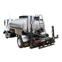
Etnyre Black-Topper Operation Maintenance Safety (99 pages)
Asphalt Distributor with Touch Screen Controls
Brand:
Etnyre
| Category:
Construction Equipment
| Size: 21 MB
Table of Contents
Warranty
2
Table of Contents
4
Warning and Instruction Plates
6
Figure 1. Location of Warning and Instruction Plates
6
General Safety Instructions
8
Safety Precautions, Hazard Seriousness Level
8
Fluoroelastomer Handling
9
Foaming
11
Asphalt Institute
11
Figure 2. Flashing Low Level Indicator
11
Figure 3. Low Tank - Burners Fault
11
Introduction
12
Reporting Safety Defects
12
Component Location and Identification
13
Figure 4 - Rear and Side Component Identification
13
Figure 5. Rear Component Identification
13
Figure 6. Spray Bar Component Identification
14
Figure 7 - Hydraulic Tank Component Identificaiton
14
Cab Touch Screen Control Panel
15
Figure 8 - Cab Control Panel Components
15
Rear Touch Screen Control Panel
17
Figure 9 - Rear Control Panel Components
17
Preparing for Operation
18
Settings
19
Figure 10 - Gear Icon
19
Figure 11 - Setup Button
19
Figure 12 - Setup Login Button
19
Setup
20
Figure 13 - Page 1 of Setup Screen
20
Figure 14 - Pump Threshold Description
20
Figure 15 - Reset Defaults Button
21
Calibrations
22
Figure 16 - Memory Window and Keyboard
22
Figure 17 - Machine Calibrations Button
22
Left Bar, Right Bar Smart Cylinder (Variable Width Bar Only)
23
Figure 18 - Machine Calibrations Window
23
Figure 19 - Left Bar Smart Cylinder START Calibrate Window
23
Pump EDC Threshold
24
Figure 20 - Hydraulic Pump EDC Threshold Calibration
24
Figure 21 - Pump Calibration Fault
24
Ground Speed Radar Calibration
25
Figure 22 - Ground Speed Radar Calibration
25
Figure 23 - Radar Height and Angle
25
Tank Level Sensor Calibration
26
Joysticks and Thumbwheels
26
Figure 24 - Tank Level Sensor Calibration
26
Figure 25 - Calibrate Empty and Calibrate Full Buttons
26
Setup
27
Spray Marker Valves
27
Power Return Spray
27
Figure 26 - Page 2 of Setup Screen
27
Figure 27 - Metric Units White Bar
27
Setup
28
USB / Computer Update
28
Fault Control
28
Initialize Leds
28
Figure 28 - Page 3 of Setup Screen
28
Figure 29 - Faults Disabled Icon
28
Display
29
Backlight
29
Touch Point
29
Voltage / Temp
29
Figure 30 - Display Screen
29
Color Scheme
30
Volume
30
Figure 31 - Front Display / Rear Display
30
Figure 32 - USB Icons
30
Figure 33 - Speaker Volume
30
Faults
31
Under Application
31
Over Application
31
EDC Feedback Range
31
Zero Motor Speed (Motor Feedback)
31
Pump Calibration
31
Radar Calibration
31
Asphalt Temperature Sensor
31
Figure 34 - Page 1 of Faults Screen
31
Hydraulic Temperature Hot
32
Tank Level Sensor
32
Tank Level - Bar Circ
32
Tank Level - Burners
32
Front Display
32
Rear Display
32
Front I/O Module
32
Left Air Output Module
32
Right Air Output Module
32
Figure 35 - Page 2 of Faults Screen
32
Hydraulic Output Module
33
Accessories Output Module
33
Other CAN Modules
33
Computer Ios
33
Left Variable Width Spray Bar
33
Right Variable Width Spray Bar
33
Diagnostics
34
Spray Valves
34
Figure 36 - Page 1 of Diagnostics Screen
34
Figure 37 - Page 2 of Diagnostics Screen
35
Help
36
View Pdfs
36
Figure 38 - Help Screen
36
Figure 39 - Black-Topper Computator
36
Information
37
Pump Meter
37
Figure 40 - Information Screen
37
Figure 41 - Pump Meter
37
Lights
38
Maximum Current Draw [Amps]
38
Figure 42 - Lights Icon Button
38
Figure 43 - Lights Screen
38
Figure 44 - Lights Name Keyboard
38
Operation
39
Main Controls
39
Operation Mode
39
Pump Control
39
Figure 45 - Home Screen
39
Figure 46 - Operation Mode
39
Figure 47 - Pump Control
39
Two Speed Motor (if Equipped)
40
Smart Clean (if Equipped)
40
Figure 48 - Motor Speed
40
Burner Control
41
Figure 49 - Burner Control
41
Figure 50 - Smart Clean Window
41
Ignition and out Fire Control
42
Fuel Oil Burners
42
Tank Valve (if Equipped)
43
Suck Back Bar Circ (if Equipped)
43
Figure 51 - Tank Valve
43
Figure 52 - Front Load Valve
43
Figure 53 - Suck Back Bar Circ
43
Figure 54 - Operation Page 2 Screen
43
Taper Switch (Optional)
44
Marker Valves
44
Wash Pump (if Equipped)
44
Figure 55 - Taper Switch
44
Figure 56 - Marker Valves
44
Figure 57 - Wash Pump
44
Spray Totals
45
Log Spray Totals
45
Figure 58 - Operation Page 3 Screen
45
Figure 59 - Log Spray Totals
45
Tank Capacity
46
Figure 60 - Tank Level
46
Loading through the Manhole
47
Figure 61 - Valve Positions for Loading through the Manhole
47
Loading through the Load Line
48
Connections and Preliminary Checks
48
Check Strainers
48
Using the Measuring Stick
48
Figure 62 - Using the Measuring Stick
48
Figure 63 - LOAD Operation Mode
49
Figure 64 - Increasing Pump Speed Slider
49
Figure 65 - LED Tank Gauge Bar
49
Figure 66 - Valve Positions for Loading through the Load Line
50
Circulating in the Tank
51
Figure 67 - TANK CIRC Operation Mode
51
Figure 68 - Valve Positions for Circulating in the Tank
52
Circulating in the Spray Bar
53
Figure 69 - BAR CIRC Operation Mode
53
Figure 70 - Valve Positions for Circulating in the Spray Bar
54
Spraying through the Spray Bar
55
Figure 71 - Bar Latch Symbol
55
Figure 72 - Valve Positions for Spraying through the Spray Bar
56
Spray Bar Suck Back
57
Figure 73 - Suck Back Operation Mode
57
Figure 74 - Valve Positions for Spray Bar Suck Back
58
Figure 75 - Open Nozzles Flashing Green
59
Figure 76 - Auto Spray Mode
59
Figure 77- Manual Spray Mode
59
Nozzle Range Indicator
60
Spraying with the Hand Spray
61
Figure 78 - Handspray Operation Mode
61
Figure 79 - Valve Positions for Spraying with the Hand Spray
62
Handspray Suckback
63
Suckback
63
Suck Back Override
64
Figure 80 - Suck Back Override
64
Bar Flushing Operations
65
Figure 81 - Flush Operation Mode
65
Figure 82. Valve Positions for Flushing
66
Unload Operations
67
With External Pump
67
Figure 83 - Unload Operation AUTO Mode
67
Figure 84. Valve Positions for Unload with External Pump
68
With Distributor Pump
69
Figure 85 - Unload Operation MANUAL Mode
69
Figure 86. Valve Positions for Unload with Distributor Pump
70
Transfer Operations
71
Figure 87 - Transfer Operation Mode
71
Figure 88. Valve Positions for Transfer
72
Heating Product in Distributors
73
Heating with Propane Burners
73
Figure 89. Ignition & out Fire Control System
74
Heating with Fuel Oil Burners
76
Troubleshooting
78
Maintenance
79
Figure 90. Gun Assembly
79
Figure 91. Electrode Setting
79
Figure 92. Right Hand / Left Hand Electrodes
79
Figure 93. Hydraulic Motor
80
Figure 94. Etnyre Asphalt Pump
81
Figure 95. Fluid Cleanliness Chart
83
Electrical Schematic
85
Lubrication Chart
93
Valve Abbreviations - Standard Bar
94
Valve Abbreviations - Variable Widthbar
95
USB Application Update
96
APPENDIX D - Default GPM & LPM Chart
97
Etnyre Spraybar Nozzles
98
Serial Number Plate Location
99
Advertisement
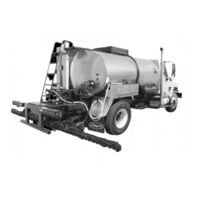
Etnyre Black-Topper Operation, Maintenance And Safety Manual (71 pages)
Centennial Series Asphalt Distributor With BT 1 Controls
Brand:
Etnyre
| Category:
Construction Equipment
| Size: 7 MB
Table of Contents
Table of Contents
4
Warning and Instruction Plates
6
Figure 1. Location of Warning and Instruction Plates
6
General Safety Instructions
8
Safety Precautions, Hazard Seriousness Level
8
Warnings
9
Fluoroelastomer Handling
9
Foaming
11
Asphalt Institute
11
Introduction
12
Reporting Safety Defects
12
Figure 2. Rear and Side Component Identification
13
Figure 3. Rear Component Identification
13
Component Location and Identification
13
Rear and Side Components
13
Figure 4 Spray Bar Component Identification
14
Figure 5. Hydraulic Tank Component Identification
14
Spray Bar Components
14
Hydraulic Tank Components
14
Figure 6. Cab Control Panel Components
15
Cab Control Panel
15
Figure 7. Rear Control Panel Components
17
Rear Control Panel
17
Preparing for Operation
20
Setting up the Computer
20
First Screen
20
Second Screen
20
Third Screen
20
Fourth Screen
21
Fifth Screen
21
Sixth Screen
21
Engaging Pump on PTO Equipped Distributors
21
Manual Transmissions
21
Automatic Transmissions
21
Spraying Operations
22
Figure 8. Adjusting the Spray Bar Nozzles
23
Figure 9. Adjusting the Spray Bar Height
23
Setting the Digital Memory Presets
23
Adjusting the Spray Bar Nozzle Angle
23
Adjusting the Spray Bar Height
23
Preparing for Operation
24
Operation
24
Tank Capacity
24
Operation Screens
24
First Operating Screen
24
Second Operating Screen
24
Third Operating Screen
25
Information Messages
25
Loading
27
Loading through the Manhole
27
Figure 11. Valve Positions for Loading through the Manhole
27
Loading through the Load Line Connections and Preliminary Checks
28
Check Strainers
28
Using the Measuring Stick
28
Figure 12. Using the Measuring Stick
28
Loading through the Load Line
29
Figure 13 Valve Positions for Loading through the Load Line
29
Figure 14. Valve Positions for Circulating in the Tank
31
Circulating in the Tank
31
Figure 15. Valve Positions for Circulating in the Bar
33
Circulating Product in the Bar
33
Figure 16. Valve Positions for Spraying through the Bar
35
Spraying through the Bar
35
Figure 17. Valve Positions for Handspray
36
Hand Spraying
36
Figure 18. Valve Positions for Spray Bar Suck Back
37
Spray Bar Suckback
37
Bar Suck Back Override
39
Handspray Suckback
40
Flushing Operations
41
Bar Flush (Auto)
41
Figure 19. Valve Postions for Flushing
41
Bar Flush (Manual)
42
Enviro-Flush System (OPTIONAL)
43
Figure 20. Enviro-Flush Flow Diagram
43
Recycle Enviro-Flush
44
Figure 21. Recirculating Flushing System Operation
44
Figure 22. Valve Positions for Unload with External Pump
45
Unload Operations with External Pump
45
Figure 23. Valve Positions for Unload with Distributor Pump
47
Unload Operations with Distributor Pump
47
Figure 24. Valve Positions for Transfer
49
Transfer Operations
49
Heating Product in Distributors
51
Heating with Propane Burners
51
Propane Requirements
51
Manual Ignition Control
52
Figure 25. Manual Ignition Control
52
Ignition and out Fire Control
53
Figure 26. Ignition and out Fire Control
53
Thermostatic Control
55
Heating with Fuel Oil Burners
56
Ignition and out Fire Control
57
Figure 27. Fuel Oil Burner System
57
Thermostatic Control
58
Troubleshooting
59
Figure 28. Gun Assembly
61
Figure 29. Right Hand / Left Hand Electrodes
61
Figure 30. Electrode Setting
61
Maintenance
61
Gun Assembly
61
Electrode Settings
61
Figure 31. Hydraulic Motor
62
Check Ignition Transformer Spark
62
Fire Burners
62
Replacing Speed Pickup
62
Servicing the Etnyre P-15 Pump
63
Vacuum Check
63
Pump Disassembly and Inspection
63
Impeller Installation and Pump Assembly
63
Figure 32. Etnyre Asphalt Pump
63
General Fuel Data and Heating Terminology
64
Fuel Data
64
Approximate Burner Fuel Consumption
64
Heating Terminology
64
Hydraulic Fluid Requirements
65
General Information
65
Viscosity & Temperature Requirements
65
Contamination Levels
66
Figure 33. Fluid Cleanliness Chart
66
Lubrication Chart
68
Etnyre Spraybar Nozzles
69
Figure 34. Serial Number Plate Location
70
Serial Number Plate Location
70
Decimal Equivalent Chart
70
Etnyre Black-Topper Manual Supplement (38 pages)
Brand:
Etnyre
| Category:
Amplifier
| Size: 1 MB
Table of Contents
How to Order Parts
2
Warranty
2
Table of Contents
3
Safety Instructions
4
Loading Tank
4
Heating Asphalt
4
Safety Instructions
5
Hydrostatic Start - up Instructions
6
Dynapower Generation II Pump Rotation Rear View
7
Acceptable Hydraulic Fluids
8
Instructions for Calibration of Distributor
9
Etnyre Measuring Stick
9
General Fuel Data and Heating Terminology
10
Service Procedure Wear Check - Etnyre P-15 Pump
11
Impeller Installation
11
Etnyre Spraybar Nozzles
12
Spraybar Nozzle Adjustment
12
Spraybar Flow Diagrams
13
Washout and Drain Procedure
13
Turn Up, Shift, and Carrier Assemblies
14
Heavy Duty Spray Bar Carrier
14
Hydraulic Spray Bar Raise
15
Heavy Duty Spray Bar Carrier
15
Wiring Diagram - Bar On/Off Hvy Duty Carrier
16
Hydraulic Schematic - Bar Raise - Hvy Duty Bar Carrier
16
Bitumeter Assembly - Digital
17
Hydraulic Universal & Tachometer Drive - Digital
18
Wiring Diagram - Digital - BT W/Fc or TUC Spray Bar
19
Wiring Diagram - Digital - BT W/Sam Type Spray Bar
19
High Pressure (Fuel Oil) Burners - Start-Up Instructions 19 High Pressure (Fuel Oil) Burners - Oper Instructions
22
High Pressure ( Fuel Oil ) Burner Installation
23
High Pressure Burner Hydraulic Valve Assembly
24
Igniter Burner Wiring - Hi Pressure (Fuel Oil) Burners
25
RAI Blower W/Viking Oil Pump
26
Hydrostatic Blower Drive Low Pressure Burners Only
27
Hydrostatic Drive - PTO - High or Low Press Burners - W/Dynapower Pump & Aux Pump Blower Drive
29
Hydrostatic Drive - PTO - LPG or Kerosene Generating Burners - W/Dynapower Generation II Pump & Motor
31
Pump Drive - Crankshaft - High or Low Pressure Burners - W/Dynapower Pump & Auxillary Pump
33
Pump Drive - Crankshaft- LPG or Kerosene Generating Burners - W/Dynapower Generation II Pump & Motor
34
Tank Gauge Assembly
35
Portable Burner
36
Liquid Propane - Bottle System
36
Transmission Assembly - Funk 3 - Speed
37
Reporting Safety Defects
38
Advertisement
Etnyre Black-Topper Manual (20 pages)
Standard Spraybar with BT-1 Keypad Controls
Brand:
Etnyre
| Category:
Utility Vehicle
| Size: 9 MB
Table of Contents
Etnyre Spray Bar Nozzles
2
Table of Contents
3
Bar Suck Back Override
4
Control Panels
5
Load through Manhole
6
Load through Load Line
7
Circulate in Tank
8
Circulate in Bar
9
Spray
10
Suckback Spraybar
11
Handspray
12
Suckback Handspray
13
Unload (with External Pump)
14
Unload (with Distributor Pump)
15
Transfer
16
Flushing
17
Flushing Bar
18
Front Fill (Optional Equipment)
19
Etnyre Black-Topper Manual (17 pages)
Standard Spraybar with Touch Screen Controls
Brand:
Etnyre
| Category:
Utility Vehicle
| Size: 12 MB
Table of Contents
Etnyre Spray Bar Nozzles
2
Table of Contents
3
Bar Suck Back Override
4
Control Panels
5
Load through Manhole
6
Load through Load Line
7
Circulate in Tank
8
Circulate in Bar
9
Spray
10
Suckback Spraybar
11
Handspray
12
Suckback Handspray
13
Flushing Bar - AUTO
14
Flushing Bar - MANUAL
15
Unload (with External Pump)
16
Unload (with Distributor Pump)
17
Transfer
17
Etnyre Black-Topper Manual (11 pages)
Asphalt Distributor With Touch Screen Controls
Brand:
Etnyre
| Category:
Construction Equipment
| Size: 5 MB
Table of Contents
Table of Contents
1
Smart Clean Operations
4
Suck Back Procedure
6
Spray Bar Smart Clean Procedure
7
Spray Bar/Asphalt Pump Smartclean Figures
7
Empty Smart Clean Tank into Main Tank
10
Adjusting Preset Smart Clean Functions
10
Etnyre Black-Topper Operation (4 pages)
Enviro-Flush, Recirculating Flushing System
Brand:
Etnyre
| Category:
Construction Equipment
| Size: 0 MB
Advertisement
Related Products
Etnyre Black-Topper Centennial Distributor
Etnyre Black-Topper BT
Etnyre Black-Topper BX
Etnyre Black-Topper BT/SAM
Etnyre Black-Topper CENTENNIAL
Etnyre Black-Topper Shooter II
Etnyre Black-Topper BT-1 Distributors 2009
Etnyre Black-Topper BT-1 Distributors 2010
Etnyre Black-Topper BT-1 Distributors 2011
Etnyre Black-Topper BT-1 Distributors 2012
Etnyre Categories
Utility Vehicle
Construction Equipment
Amplifier
Industrial Equipment
More Etnyre Manuals
Login
Sign In
OR
Sign in with Facebook
Sign in with Google
Upload manual
Upload from disk
Upload from URL