Advertisement
Quick Links
www.ti.com
User's Guide
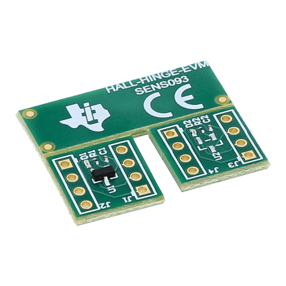
Hall-Hinge-EVM
This user's guide describes the characteristics, operation, and use of the HALL-HINGE Evaluation Module
(EVM). This EVM is designed with accompany
hinge lid closure apparatus used commonly in laptop lid closures and other lid and door detection applications.
The design is compatible with the
portfolio. This document includes a schematic,
of materials
(BOM).
1
Overview..................................................................................................................................................................................2
2 Hardware.................................................................................................................................................................................
3
Operation.................................................................................................................................................................................3
4 Schematics, PCB Layout, and Bill of Materials...................................................................................................................
Trademarks
All trademarks are the property of their respective owners.
SLYU062 - FEBRUARY 2022
Submit Document Feedback
ABSTRACT
3D printed structures
HALL-ADAPTER-EVM
to allow broader testing of TI's magnetic sensing
reference printed circuit board (PCB)
Figure 1-1. Hall-Hinge-EVM
Table of Contents
Copyright © 2022 Texas Instruments Incorporated
and magnet to evaluate TMAG5231B1 in a
layout, and a
Table of Contents
complete bill
3
9
Hall-Hinge-EVM
1
Advertisement

Subscribe to Our Youtube Channel
Related Manuals for Texas Instruments Hall-Hinge-EVM


Summary of Contents for Texas Instruments Hall-Hinge-EVM
- Page 1 Figure 1-1. Hall-Hinge-EVM Table of Contents Overview....................................2 2 Hardware....................................Operation....................................3 4 Schematics, PCB Layout, and Bill of Materials........................Trademarks All trademarks are the property of their respective owners. SLYU062 – FEBRUARY 2022 Hall-Hinge-EVM Submit Document Feedback Copyright © 2022 Texas Instruments Incorporated...
-
Page 2: Overview
1 Overview The HALL-HINGE-EVM is composed of various 3D printed structures which combine to assist with evaluation of lid closure detection. The sensor and magnet positions are independently adjustable to demonstrate the flexibility of Hall-effect sensors in this function type. -
Page 3: Hardware
Final assembly of the 3D printed structures will be required to complete EVM setup. This may be done with either HALL-HINGE-EVM or with HALL-ADAPATER-EVM. The following steps walk through the procedure to evaluate TMAG5231 with the HALL-HINGE-EVM. If desired, the 3D assembly may be downloaded, edited and reprinted as needed from SLYU062.zip. - Page 4 Operation www.ti.com Figure 3-4. SENS093_Bracket & SENS093_Slider Figure 3-5. SENS093_Protractor Hall-Hinge-EVM SLYU062 – FEBRUARY 2022 Submit Document Feedback Copyright © 2022 Texas Instruments Incorporated...
- Page 5 Operation Figure 3-6. B222 - N42 Cube Magnet 1. Locate the HALL-HINGE-EVM PCBs. TMAG5231 may be evaluated on this PCB with or without the use of the 3D structures. The device may be powered by connecting a voltage source or battery as indicated in Figure 3-7.
- Page 6 The direction of magnet polarization may also be adjusted freely. b. You can adjust the vertical position of the magnet by turning the screw shown in Figure 3-12. Hall-Hinge-EVM SLYU062 – FEBRUARY 2022 Submit Document Feedback Copyright © 2022 Texas Instruments Incorporated...
- Page 7 You can fix the SENS093_Slider position by tightening the set screw shown in Figure 3-13. Figure 3-13. Set Screw 6. Optional: Insert the Protractor on to the Track from bottom as shown in Figure 3-14. SLYU062 – FEBRUARY 2022 Hall-Hinge-EVM Submit Document Feedback Copyright © 2022 Texas Instruments Incorporated...
- Page 8 Figure 3-15. Protractor Degree Intervals b. The bottom edge of the arm aligns with the protractor to mark for angle measurements as shown in Figure 3-16. Hall-Hinge-EVM SLYU062 – FEBRUARY 2022 Submit Document Feedback Copyright © 2022 Texas Instruments Incorporated...
-
Page 9: Schematics, Pcb Layout, And Bill Of Materials
Schematics, PCB Layout, and Bill of Materials Figure 3-16. Protractor Angle Alignment 7. Apply 3.3 V to Vcc (accepts 1.65V - 5.5 V) to power Hall-Hinge-EVM. 8. Adjust the arm position and observe the output LED. The LED will illuminate when device output is activated by a magnetic field. - Page 10 Schematics, PCB Layout, and Bill of Materials www.ti.com PCB Layout Figure 4-2 through Figure 4-4 show the PCB layers of the EVM. Figure 4-2. Top View Figure 4-3. Top Copper Hall-Hinge-EVM SLYU062 – FEBRUARY 2022 Submit Document Feedback Copyright © 2022 Texas Instruments Incorporated...
- Page 11 SML-P11UTT86R ROHM Chip LED 2-Pin 0402 R1, R2 RES, 604, 1%, 0.05 0201 RC0201FR-07604 Yageo America W, 0201 Low-Power, Hall SOT-23-3 TMAG5231B1DQ Texas Instruments Effect Switch DBZR SLYU062 – FEBRUARY 2022 Hall-Hinge-EVM Submit Document Feedback Copyright © 2022 Texas Instruments Incorporated...
- Page 12 TI products. TI’s provision of these resources does not expand or otherwise alter TI’s applicable warranties or warranty disclaimers for TI products. TI objects to and rejects any additional or different terms you may have proposed. IMPORTANT NOTICE Mailing Address: Texas Instruments, Post Office Box 655303, Dallas, Texas 75265 Copyright © 2022, Texas Instruments Incorporated...
Need help?
Do you have a question about the Hall-Hinge-EVM and is the answer not in the manual?
Questions and answers