
Related Manuals for Emerson Machinery Health PR 642 Series


Summary of Contents for Emerson Machinery Health PR 642 Series
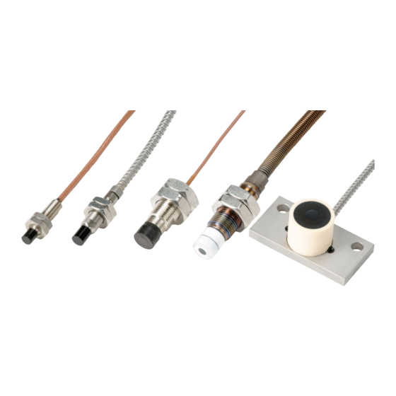
- Page 1 Installation Guide MHM-97857 , Rev 1.5 January 2020 ™ Machinery Health Sensor PR 642x, Eddy Current Sensors...
- Page 2 Information in this document is subject to change without notice and does not represent a commitment on the part of Emerson. The information in this manual is not all-inclusive and cannot cover all unique situations.
-
Page 3: Table Of Contents
Installation Guide Contents MHM-97857 January 2020 Contents Chapter 1 General.......................... 5 1.1 Using this manual..........................5 1.2 Symbol explanation.......................... 5 1.3 Liability and guarantee........................6 1.4 Incoming goods inspection......................6 1.5 Technical support..........................6 1.6 Storage and transport........................7 1.7 Disposal of the device........................7 1.8 China RoHS Compliance........................ - Page 4 Contents Installation Guide January 2020 MHM-97857 MHM-97857, Rev 1.5...
-
Page 5: Chapter 1 General
Installation Guide General MHM-97857 January 2020 General Using this manual This manual contains information concerning the proper and correct use of the PR 6422, PR 6423, PR 6424, PR 6425 and PR 6426 eddy current transducers. For correct and safe use of this device read the entire operating manual prior to installing and operating the device. -
Page 6: Liability And Guarantee
Product Service Center. Before shipping this product, contact Emerson Product Support to obtain a Return Materials Authorization (RMA) number and receive additional instructions. Product Support Emerson provides a variety of ways to reach your Product Support team to get the answers you need when you need them: Phone Toll free 800.833.8314 (U.S. -
Page 7: Storage And Transport
Installation Guide General MHM-97857 January 2020 To view toll free numbers for specific countries, visit http://www.emersonprocess.com/ technicalsupport. Note If the equipment has been exposed to a hazardous substance, a Material Safety Data Sheet (MSDS) must be included with the returned materials. An MSDS is required by law to be available to people exposed to specific hazardous substances. -
Page 8: Installation Awareness
General Installation Guide January 2020 MHM-97857 Installation awareness Note When planning a measurement, observe the following items: • Consider environmental conditions which might have an influence on the measurement such as temperature, humidity, substances aggressive to the sensor, and pollution. •... -
Page 9: Chapter 2 Safety Instructions
Installation Guide Safety Instructions MHM-97857 January 2020 Safety Instructions To ensure safe operation, carefully observe all instructions in this manual. The correct and safe use of this device requires that operating and service personnel both understand and comply with general safety guidelines and observe the special safety comments listed in this manual. - Page 10 Safety Instructions Installation Guide January 2020 MHM-97857 MHM-97857, Rev 1.5...
-
Page 11: Application And Design
Installation Guide Application and Design MHM-97857 January 2020 Application and Design The Measuring Chain Together with signal converters of the series CON 0x1, integrated converters of the MMS 3000 series, or the CSI 9360 transmitter, the sensors PR 6422 to PR 6426 form eddy current measuring chains for contactless distance, vibration and speed measurements. - Page 12 Application and Design Installation Guide January 2020 MHM-97857 MHM-97857, Rev 1.5...
-
Page 13: Installation And Mounting
(refer to Requirements and hints for the sensor mounting). To measure shaft vibration, Emerson recommends using a sensor holder between bearing and turbine housing as close as possible to the rotor. Figure 4-1: Example scheme where to place the sensors... -
Page 14: Mount The Sensor
Installation and Mounting Installation Guide January 2020 MHM-97857 Mount the sensor The following steps describe the mounting of sensor types PR 6422, PR 6423, PR 6424 and PR 6425. For mounting hints regarding the PR 6426 see PR 6426 installation. See also the respective converter manuals as listed inTable 1-1 for further details regarding sensor... - Page 15 Installation Guide Installation and Mounting MHM-97857 January 2020 Sensor fastening • Use the enclosed nuts when installing sensors with mounting threads • When installing sensors with mounting threads captive nuts must be used to avoid loosen of the sensor. Loose parts can fall into the machine and cause damages. A ®...
- Page 16 Installation and Mounting Installation Guide January 2020 MHM-97857 Figure 4-3: Maximum axial tilting if using PR 6422, PR 6423, PR 6424 or PR 6425 S: distance between measuring target and sensor head Alpha: max. axial tilting angle < 2° MHM-97857, Rev 1.5...
- Page 17 Installation Guide Installation and Mounting MHM-97857 January 2020 Figure 4-4: Maximum axial tilting if using PR 6426 S: distance between measuring target and sensor head Alpha: max. axial tilting angle < 1.6° Maximum tangential offset Ensure the maximum tangential offset matches the values in Table 4-1.
- Page 18 Installation and Mounting Installation Guide January 2020 MHM-97857 Figure 4-5: Maximum tangential offset X: max. tangential offset D: shaft diameter Minimum measuring area Ensure that the minimum measuring area matches the values in Table 4-2. Figure 4-6 defines of the minimum measuring area. Table 4-2: Minimum measuring area Sensor type X minimum...
-
Page 19: Pr 6426 Installation
Installation Guide Installation and Mounting MHM-97857 January 2020 Figure 4-6: Minimum measuring area 4.3.2 PR 6426 installation Figure 4-7 shows an installation example for the sensor PR 6426. Its reference area is the mounting plate. The nominal distance of the mounting plate to the measuring target in the center position is approx. -
Page 20: Wiring Hints
Installation and Mounting Installation Guide January 2020 MHM-97857 Figure 4-7: Mounting example PR 6426 Wiring hints This section contains general information and wiring hints regarding the sensor cable installation. The necessary measures for the proper cable installation depend always on the situation on-site. -
Page 21: Sensor Cables With Lemo Adapter Plug
Installation Guide Installation and Mounting MHM-97857 January 2020 • Do not bend or twist the sensor cables. Cables and connectors must be movable when the sensor is screwed into the holder. • Do not squeeze the cable; for example, between metal plates for fixing. Squeezing the cable will damage the outer isolation, which could allow oil into the cable or causes short-circuits. - Page 22 Installation and Mounting Installation Guide January 2020 MHM-97857 Figure 4-9: Measurement specifications for applying shrink sleeve A: Shrink sleeve B: Adapter plug C: Sensor cable Apply shrink sleeve to a connector 1. At the open adapter connection, push the shrink sleeve over one connector so that the sleeve completely covers the sensor cable.
-
Page 23: Technical Data
Installation Guide Technical data MHM-97857 January 2020 Technical data Only specifications with tolerances are guaranteed. Data without tolerance or without error limits are informative data and not guaranteed. All specifications are valid for a measuring chain consisting of a sensor PR 6422, PR 6423, PR 6424, PR 6425 or PR 6426 and one of the following converters CON 011, 021, 031 or 041 respectively an integrated converter in a MMS 3000 transmitter adjusted on it. -
Page 24: Measuring Ranges And Sensitivity
Technical data Installation Guide January 2020 MHM-97857 Measuring ranges and sensitivity Sensor PR 6422 PR 6423 PR 6424 PR 6425 PR 6426 Nominal ±0,5 mm ±1,0 mm ±2,0 mm ±2,0 mm ±4,0 mm measuring range, static measurement Nominal 25 ... 250 µm 50 ... -
Page 25: Environmental Conditions
Installation Guide Technical data MHM-97857 January 2020 Environmental conditions Environmental temperature Reference value +23°C −35°C ... +180°C (short time , up to +200°C) Nominal operating range PR 6422 ... PR 6424, PR 6426 PR 6425 only sensor and first part of the cable - nominal operating range permanent 0 ... - Page 26 Technical data Installation Guide January 2020 MHM-97857 Table 5-1: Additional error Sensor type Temperature range Zero point Sensitivity PR 6425 at +300 … +380°C 0.8% per 10 K PR 6426 at +23 ...+100°C ≤ -0,3 % per 10 K ≤ 0,15 % per 10 K at +100 ...+180°C ≤...
-
Page 27: Chapter 6 Drawings
Installation Guide Drawings MHM-97857 January 2020 Drawings Figure 6-1: Dimensions standard types PR 6422 MHM-97857, Rev 1.5... - Page 28 Drawings Installation Guide January 2020 MHM-97857 Figure 6-2: Dimensions standard types PR 6423 MHM-97857, Rev 1.5...
- Page 29 Installation Guide Drawings MHM-97857 January 2020 Figure 6-3: Dimensions standard types PR 6424 MHM-97857, Rev 1.5...
- Page 30 Drawings Installation Guide January 2020 MHM-97857 Figure 6-4: Dimensions standard type PR 6425 MHM-97857, Rev 1.5...
- Page 31 Installation Guide Drawings MHM-97857 January 2020 Figure 6-5: Dimensions standard types PR 6426 MHM-97857, Rev 1.5...
- Page 32 Drawings Installation Guide January 2020 MHM-97857 MHM-97857, Rev 1.5...
-
Page 33: Chapter 7 Order Matrix
Installation Guide Order Matrix MHM-97857 January 2020 Order Matrix Different sensor versions of the PR642x can be set up by means of the following order matrix. PR 6422/XXX-XXX Order Matrix PR 6422/ Sleeve Thread M6x0.5 ¼-28UNF-2A Armored Cable WITH WITHOUT Total Sensor Length 0(Cx=25 mm), 1(30 mm), 2(40 mm), C=Cx+5.3 mm... - Page 34 Order Matrix Installation Guide January 2020 MHM-97857 PR 6424/XXX-XXX Order Matrix PR 6424/ Sleeve Thread M18x1.5 Armored Cable WITH WITHOUT Total Sensor Length 0(Cx=40 mm), 1(50 mm), 2(60 mm), C=Cx+12.5 mm 3(70 mm), 4(80 mm), 5(90 mm), 6(100 mm), 7(110 mm), 8(120 mm), 9(130 mm), A(140 mm), B(150 mm), C(160 mm), D(170 mm), E(180 mm), F(190 mm), G(200 mm), H(210 mm),...
- Page 35 Installation Guide Order Matrix MHM-97857 January 2020 Order Matrix PR 6426/ Total Cable Length 0(4 m), 1(5 m), 2(6 m), 3(8 m), 4(10 Cable End LEMO OPEN MHM-97857, Rev 1.5...
- Page 36 Order Matrix Installation Guide January 2020 MHM-97857 MHM-97857, Rev 1.5...
-
Page 37: Chapter 8 Certificates
Installation Guide Certificates MHM-97857 January 2020 Certificates MHM-97857, Rev 1.5... - Page 38 Certificates Installation Guide January 2020 MHM-97857 MHM-97857, Rev 1.5...
- Page 39 Installation Guide MHM-97857 January 2020 MHM-97857, Rev 1.5...
- Page 40 All rights reserved. AMS is a mark of one of the Emerson group of companies. The Emerson logo is a trademark and service mark of Emerson Electric Co. All other marks are the property of their...
Need help?
Do you have a question about the Machinery Health PR 642 Series and is the answer not in the manual?
Questions and answers