Table of Contents
Advertisement
Quick Links
Download this manual
See also:
Reference Manual
Advertisement
Table of Contents

Related Manuals for Intermec 6710


Summary of Contents for Intermec 6710
- Page 1 6710 Access Point USER’S GUIDE " " " " " " " " " " " " " " " " " " " " " " " " " " " " P/N 961-047-081 Revision C July 1998...
- Page 2 Intermec Technologies Corporation, and shall be returned to Inter- mec Technologies Corporation upon written request. If a purchase, license, or nondisclosure agreement has been executed, the terms of that agreement shall govern this document.
- Page 3 " NOTICE FCC rules section 15.203 and Canada’s RSS-210 require that this device be oper- ated using an antenna furnished by Intermec Technologies Corporation. The an- tenna coupling on this product has been designed to accept only antennas manufactured by us. Use of an antenna other than that furnished with the equip- ment is prohibited by FCC and Industry Canada rules.
- Page 4 Canadian 2.4 GHz Radio License " NOTICE This device requires a radio license, unless it is installed totally inside a building. (Users must obtain this license) Une licence radio est requise pour ces dispositifs, sauf pour ceux installés tout à fait à...
- Page 5 CAUTION: Intermec Technologies Corporation suggests you buy cables from us to connect with other devices. Our cables are safe, meet FCC rules, and suit our products. Other cables may not be tested. They may cause problems from electrostatic discharge or induced energy. Our...
-
Page 7: Table Of Contents
..............6710 Access Point User’s Guide CONTENTS "... - Page 8 Horizontal (Tabletop) Mount Vertical and Ceiling Mounts 6710 Access Point User’s Guide ............
- Page 9 ... . . 4-12 4-12 4-14 4-16 4-16 4-17 4-18 4-19 4-19 4-20 4-21 ..4-21 4-21 4-21 4-22 6710 Access Point User’s Guide...
- Page 10 Example 2 6710 Access Point User’s Guide ........
- Page 11 ..4-63 4-65 4-66 4-68 4-69 4-70 4-70 ....4-70 4-71 4-72 4-72 4-73 4-73 4-73 4-74 4-74 4-74 6710 Access Point User’s Guide...
- Page 12 Fdel Command 6710 Access Point User’s Guide ........
- Page 13 ....5-22 5-23 5-23 5-23 5-23 5-24 5-24 5-24 5-25 5-25 5-25 5-26 5-26 5-26 5-26 5-26 6710 Access Point User’s Guide...
- Page 14 6710 Access Point User’s Guide .........
- Page 15 ..........6710 Access Point User’s Guide...
- Page 16 Station Mobility Mobile IP Comparison 6710 Access Point User’s Guide .......
- Page 17 ........6710 Access Point MIB Information Access to Management Information MIB-II Notes .
- Page 18 ......... . FIGURES Figure 2-1 6710 Access Points Figure 2-2 6710 Access Point Functions Figure 2-3 Sample Network Configuration Figure 2-4 Access Point Components...
- Page 19 ......... . E-13 G-10 6710 Access Point User’s Guide xiii...
- Page 20 Table G-22 powerUp GROUP Table G-23 softwareDownLoad GROUP 6710 Access Point User’s Guide ............
-
Page 21: Preface
Norand Corporation is now part of Intermec Technologies Corporation. As part of our continuing efforts to offer the broadest range of system solutions in the industry, the 6710 Access Point and other open wireless local area network (LAN) components have been merged into the INTERMEC Integrated Network Communications Architecture (INCA). - Page 22 Appendix E Appendix F Appendix G The glossary at the end of this manual lists network terms. 6710 Access Point User’s Guide Helps you prepare your site before you install the access point, and shows how to connect the access point to 10BASE-T, 10BASE2, and 10BASE5 Ethernet.
-
Page 23: Intended Audience
Related Publications The following publications are available. They include information about hardware and software products related to or used with the access point and the network on which it operates. Numbers in parentheses after the title indicate the publication’s part number. Contact your Sales Representative for ordering information. -
Page 24: System Management Publications
HP OpenView for Windows network management platform. Customer Support The goal of Intermec Technologies Corporation is 100 percent customer satisfaction. If you would like more information about the access point or other open wireless LAN system components, contact us through the Customer Response Center. -
Page 25: Features And Functional Overview
" " " " " This section describes the 6710 Access Point and how it operates on the open wireless LAN. This section also describes access point components. Description The 6710 Access Point provides transparent, wireless communications between a wired Ethernet LAN and wireless stations. -
Page 26: Bridging Functionality
Bridges are common components in wired LANs. Bridges are devices that join two or more LAN segments. This provides the appearance of a single LAN segment to the protocols and applications that operate within the LAN. 6710 Access Point User’s Guide Bridging Port 2 Port 3... - Page 27 Generally, if a bridge receives a frame for an unknown destination address on any one port, it floods the frame on all other ports. Features and Functional Overview " 6710 Access Point User’s Guide...
-
Page 28: Access Point Bridging Layer
SECTION 2 Features and Functional Overview " Access Point Bridging Layer The 6710 Access Point functions as a bridge with up to four ports: An Ethernet port. " One or two radio ports. " An Open Wireless LAN/Internet Protocol (OWL/IP) "... -
Page 29: Forwarding
These stations wake up periodically to receive messages that may have arrived while their radio was powered down. The bridging software provides a pending message delivery service, allowing frames to be held until the station is ready to receive them. 6710 Access Point User’s Guide... -
Page 30: Flooding Configurations
Two of the wireless media supported in the access point — synthesized UHF (S-UHF) and 900 MHz — provide reliable attach mechanisms, which guarantee that wireless stations are always in the access point’s forwarding database. -
Page 31: Proxy Arp Server
The Ethernet port can be configured to support 10BASE-T twisted pair, 10BASE2 thinnet, or an AUI connection. The AUI connection can support 10BASE5 thicknet or 10BASEF fiber optic connections with the appropriate media adapters. Features and Functional Overview " 6710 Access Point User’s Guide... -
Page 32: Ethernet Port Filters
For example, filters can be set to eliminate some or all IP traffic or Novell IPX traffic. 6710 Access Point User’s Guide... -
Page 33: Radio Ports
Radio Ports Each of the two radio ports in the access point are a connection into a LAN segment consisting of all wireless stations and access points that use the same wireless... -
Page 34: Owl/Ip Port
Encapsulated frames may be sent through any of the three physical ports. Access points separated by one or more routers may be thought of as originating and receiving nodes on the two sides of a tunnel that is established through the router. 2-10 6710 Access Point User’s Guide... -
Page 35: Configuration And Management
Diagnostics and Configuration Port An RS-232 configuration port is provided for direct access to the access point’s command monitor and configuration menus. Access through the diagnostics port is password-protected for security. 6710 Access Point User’s Guide 2-11... -
Page 36: Remote Access
Telnet may be used to access the access point’s configuration menus. The command interface is identical to the command interface through the diagnostics port. See Section 4, “Configuration,” for more information about access through Telnet. 2-12 6710 Access Point User’s Guide... -
Page 37: Http
The upgrade can be started immediately after downloading by swapping the active and inactive banks and rebooting. The access point can also be programmed to load the new software at a later time, such as after all access points have been upgraded or during a time of little system activity. -
Page 38: Network Management
SNMP network management platform. Additional capabilities are supported in the OWLView network management application for HP OpenView. Appendix G, “MIB,” contains the 6710 Access Point MIB. Consult the following documentation for more information on network management: NORAND Open Wireless LAN with HP OpenView for "... -
Page 39: Figure 2-3 Sample Network Configuration
PEN*KEY Computer Secondary Ethernet LAN Desktop Sample Network Configuration SECTION 2 Features and Functional Overview " Terminal Emulation Gateway 6710 Access Points Notebook 6400 (WLIF) PEN*KEY 6400 Computer Figure 2-3 6710 Access Point User’s Guide Distribution LAN Wireless Hop 2-15... -
Page 40: Components
" Components Figure 2-4 shows access point components, described on the following pages. Not shown is the mounting bracket, which attaches the access point to a wall or ceiling. 2-16 6710 Access Point User’s Guide Figure 2-4 Access Point Components... -
Page 41: Figure 2-5 Pc Card Slots
After the power-up sequence, the lights show the current operating status and indicate if a problem exists. Section 6, “Indicator Lights,” describes the lights in detail. 6710 Access Point User’s Guide Features and Functional Overview 2-17... - Page 42 Features and Functional Overview " 3. Rubber feet. Four nonskid rubber feet provide a stable base for the access point when you place it on a desktop or other horizontal surface. When the mounting bracket is installed for an access...
-
Page 43: Accessories
Accessories Power Cord The power cord connects the access point to the wall outlet. The following chart lists power cord part numbers. Country Australia Denmark Europe Italy Germany United Kingdom United States Industrial Locking Mounting Bracket The Industrial Locking Mounting Bracket “locks” the access point into the bracket. - Page 44 SECTION 2 Features and Functional Overview " 2-20 6710 Access Point User’s Guide...
-
Page 45: Installation
The access point should be properly configured before it is connected to the network. Installation " " " " " " " " " " 6710 Access Point User’s Guide Section 3 " " " " " " " "... -
Page 46: Preparing For The Installation
FCC Class B electromechanical devices should physically install the access point. Before you install the access point, unpack it and inspect it for damage or missing parts. Save all the paperwork you received. If the access point appears to be damaged, contact the Customer Response Center for instructions on returning the unit for replacement. -
Page 47: 10Base2 Components
Figure 3-2 Cable Terminator 10BASE-T Component 10BASE-T coax cable is normally used to connect the access point to an Ethernet hub. The cable has an RJ45 plug on each end (Figure 3-3). Figure 3-3 Cable With RJ45 Plugs SECTION 3 Installation "... -
Page 48: 10Base5 Components
The vampire tap is an insulation-piercing clamp device that clamps onto the coaxial cable (Figure 3-5). The vampire tap pierces the coaxial cable’s insulation and makes contact with the shield and inner conductor without cutting the cable. 6710 Access Point User’s Guide... -
Page 49: Communication Equipment
PC (personal computer) station, which should meet " the requirements outlined in the user guide for the terminal emulation program. Cable to connect the PC to the access point’s DIAG " port. The following chart lists cables. SECTION 3 Installation " 6710 Access Point User’s Guide... -
Page 50: Telnet
Telnet application. You can also use a host capable of acting as a Telnet client. Telnet VT emulator (TNVT) installed on the PC. " IP address for the access point. See Section 4 for more " information about IP addresses. Web Browser The access point’s configuration menus are designed for... -
Page 51: Finding The Best Location
Finding the Best Location Site Survey Intermec strongly recommends that Intermec or certified providers conduct a site survey to determine the ideal locations for all of your network components. A proper site survey requires special equipment and training. A site... -
Page 52: Mounting The Access Point
Ethernet” on page 3-10. 4. Make all power connections. See “Applying Power” on page 3-20. 5. Watch the indicator lights to verify that the access point is working properly. See Section 6, “Indicator Lights,” for help. 6710 Access Point User’s Guide... -
Page 53: Vertical And Ceiling Mounts
See Figure 3-6 and the procedure following it. " NOTE: If mounting the access point on a hollow wall, secure the mounting plate to a 3/4” (thick) plywood base by four 1” X 1/4” nuts, bolts, and washers. Anchor the plywood base to two separate wall studs by four 2”... -
Page 54: Connecting To Ethernet
4. Attach the access point mounting plate to the wall or ceiling with 2I x 1/4I diameter lag screws or bolts, depending upon the surface. The mounting plate must be secured to the surface by at least four anchors, one on each corner. -
Page 55: 10Base2 Ethernet
10BASE2 Ethernet The access point connects to the end or middle of the 10BASE2 cable segment. " NOTE: Cable lengths between network devices on the 10BASE2 Ethernet LAN must meet ANSI/IEEE standards. End of Segment See Figure 3-7 and the procedure following it. -
Page 56: Middle Of Segment
3. Plug the end of another Ethernet coaxial cable segment into the other open end of the T-connector. 3-12 6710 Access Point User’s Guide 10 BASE 2 10 BASE T AC INPUT 100/240 VAC 1. -
Page 57: 10Base5 Ethernet
(3). 3. Attach the vampire tap to the 10BASE5 cable, then connect the other end of the drop cable to the AUI port (2) on the tap. SECTION 3 Installation " 6710 Access Point User’s Guide 3-13... -
Page 58: Figure 3-9 N-Series Transceiver
SECTION 3 Installation " 10 BASE 2 AC INPUT 100/240 VAC 3-14 6710 Access Point User’s Guide DIAG 10 BASE T 1. Drop cable 15-pin AUI port 3. N-Series transceiver 4. 10BASE5 coax Figure 3-9 N-Series Transceiver... -
Page 59: Figure 3-5 Vampire Tap
SECTION 3 10 BASE 2 10 BASE T AC INPUT 100/240 VAC 1. Drop cable 2. 15-pin AUI port 3. Vampire tap 4. 10BASE5 coax Figure 3-10 Vampire Tap 6710 Access Point User’s Guide Installation " DIAG 3-15... -
Page 60: 10Base-T Ethernet
1. Plug the cable with RJ45 jacks (1) into the 10 BASE T port. 2. Plug the other end of the cable into RJ45 jack or hub port (2). 3-16 6710 Access Point User’s Guide 10 BASE 2 10 BASE T AC INPUT 100/240 VAC 1. -
Page 61: Installing Pc Cards
3. PC card (RM180) 4. Antenna cable 5. End plate 6. 4- - 40 captive thumb screws 7. Hex nut and lock washer (supplied with antenna cable) SECTION 3 Figure 3-12 WLIF PC Card Assembly 6710 Access Point User’s Guide Installation " 3-17... -
Page 62: Figure 3-13 900 Mhz Pc Card Assembly
3. PC card (RM160) 4. Antenna cable 5. End plate 6. 4- - 40 captive thumb screws 7. Hex nut and lock washer (supplied with antenna cable) 3-18 6710 Access Point User’s Guide Figure 3-13 900 MHz PC Card Assembly... -
Page 63: S-Uhf
7. Radio bracket 8. Conductive washer 9. End plate 10. 4- - 40 captive thumb screws 11. 4- - 40 x .25 PH 12. Antenna adapter Figure 3-14 S-UHF PC Card Assembly SECTION 3 Installation " 6710 Access Point User’s Guide 3-19... -
Page 64: Applying Power
Damage to the radio or other devices can occur with the cover removed. " NOTE: Connect the access point to an uninterruptable power source — a power source that cannot be inadvertently turned off or otherwise disconnected. Power is applied to the access point through the grounded AC INPUT connector. -
Page 65: Figure 3-15 Ac Power Input Connection
SECTION 3 Installation " 10 BASE 2 10 BASE T DIAG AC INPUT 100/240 VAC 1. Receptacle on power cord 2. Three-prong plug Figure 3-15 AC Power Input Connection 6710 Access Point User’s Guide 3-21... - Page 66 SECTION 3 Installation " 3-22 6710 Access Point User’s Guide...
-
Page 67: Configuration
" " " " " " " " DIAG Port Telnet Browser Ö Ö Ö Ö Ö Ö Ö 6710 Access Point User’s Guide Section 4 " " " " " " " " Ö Ö Ö Ö Ö Ö... -
Page 68: Creating A Local Diag Port Session
Most general purpose communications software (such as PROCOMM PLUS) supports this emulation. To create a session, see Figure 4-1 and the procedure following it. You should carefully review the procedure first to become familiar with the process. 6710 Access Point User’s Guide... -
Page 69: Figure 4-1 Local Session
1. PC with terminal emulation program 2. Cable: 321-355-001 for a 25-pin PC COM port Cable: 226-106-001 for a 9-pin PC COM port (standard null modem cable) 3. 6710 Access Point DIAG port Figure 4-1 Local Session 1. Ensure the terminal emulation program is installed on the PC. -
Page 70: Accessing The Configuration Menus
Configuration " 3. Connect the other end of the communication cable to the DIAG port on the access point. Turn the PC on. 4. After the PC boots, start the terminal emulation program. 5. Set the terminal emulation program’s options... -
Page 71: Accessing The Rom Command Monitor
Power-Up Quiet (PQ) mode and Power-Up Normal (PN) mode starts on page 5-27 in Section 5, “Software Download.” 4. See page 5-22 in Section 5, “Software Download,” for information about the ROM command monitor. SECTION 4 Configuration " 6710 Access Point User’s Guide... -
Page 72: Creating A Telnet Session
To create a Telnet session, see Figure 4-2 and the procedure following it. Ethernet LAN 1. PC or workstation with Telnet VT emulator (TNVT) 2. 6710 Access Point 6710 Access Point User’s Guide Telnet Figure 4-2 Telnet Session... -
Page 73: Default And Site Settings
3. Ensure the Telnet VT emulator is installed on the PC or workstation. 4. Open a new Telnet session on the PC or workstation. 5. Enter the access point’s IP address in the host name or IP address field. 6. See “Configuring the Access Point” on page 4-12. -
Page 74: Security
Awake Time Set Globally Value [Global Flooding] Inbound Multicast Unicast Outbound to Secondaries Multicast Unicast Outbound to Stations Multicast Unicast 6710 Access Point User’s Guide Default Site Setting CR52401 Enabled “” (empty string) Default Site Setting (Read-only) Disabled Disabled Disabled Disabled... -
Page 75: Flood Register
[Values] Value [Bridging] Bridge Priority Status Flood Register SECTION 4 Default Site Setting omde (Unique number) Enabled 2 seconds Auto Detect 00:00:00:00:00:00 Pass Unlisted Pass (Various) (Various) Pass DIX--IP--TCP--Port 00 00 Enabled Disabled 6710 Access Point User’s Guide Configuration "... -
Page 76: Security Id
Frag QFSK Retry 900 MHz radio port: Name MAC Address Status Hello Period [Falcon] File Name Mode--Channel ARP Server Mode 4-10 6710 Access Point User’s Guide Default Site Setting omdpxma (Unique number) Enabled 2 seconds NORANDOWL Master Disabled Default 200 ms... - Page 77 2 seconds synuhf_d.29k “” (empty string) (First frequency in list) Disabled High omdip (Unique number) Enabled 2 seconds Listen Unicast (None) Pass Unlisted Pass (Various subtypes) (Various settings) Pass DIX--IP--TCP--Port 00 00 6710 Access Point User’s Guide Configuration " 4-11...
-
Page 78: Configuring The Access Point
Enter the password (case insensitive) to display the Main Menu. The default password is CR52401. Main Menu After you enter the top-level password, the Main Menu appears: 4-12 6710 Access Point User’s Guide 0.0.0.0 (Unique 10-digit number.) All rights reserved. - Page 79 4-7. Read Load the most recent configuration from EEPROM. The configuration that was written to EEPROM since the access point was last rebooted becomes the new configuration. SECTION 4 Configuration " 6710 Access Point User’s Guide 4-13...
-
Page 80: Using The View Command
View at the command prompt. The Main Options Menu appears: The following chart describes how to use the options. 4-14 6710 Access Point User’s Guide The access point’s configuration is stored in EEPROM. You reprogram the EEPROM whenever you change the configuration, write (save) the new configuration to EEPROM, and reboot the access point. - Page 81 Also use these keys to select the desired setting. [¬], [Esc], or [Backspace] Exit a menu or prompt. [Esc] Cancel editing. [Enter] Complete editing. SECTION 4 Configuration " 6710 Access Point User’s Guide 4-15...
-
Page 82: Tcp/Ip Options
If you are installing this access point on a new " Ethernet segment that is not going to connect to the Internet, try using this Class B address: 172.16.h.h 4-16 6710 Access Point User’s Guide 0.0.0.0 255.255.255.0 0.0.0.0 <DIX> <Enabled, if IP address is zero>... -
Page 83: Ip Subnet Mask
IP Address, you may want to use a subnet mask of 255.255.248.0. This mask provides the network 172.16 with 30 subnets of 2046 computers each. The IP address breakdown is: SECTION 4 Configuration " 6710 Access Point User’s Guide 4-17... -
Page 84: Ip Router
IP Subnet Mask option. IP Router " NOTE: The IP address of the router is required only if this access point will communicate with devices on the other side of the router. IP Router identifies the default router used to forward data frames to addresses on another subnet. -
Page 85: Ip Frame Type
IP frames. Select 802.3 if other network computers use SNAP encapsulation for IP frames. DHCP DHCP provides a way for this access point (the client) to obtain IP addresses from a DHCP server on the network. Settings are: Enabled... -
Page 86: Dhcp Server Name
If you are using OWL/IP tunneling, you should not use DHCP to allocate IP addresses to super root candidates or designated bridges unless a permanent lease is used, and the access point is rebooted after getting an address. OWL/IP options start on page 4-79. -
Page 87: Bootp Operation
Infinite Leases A DHCP server may be configured to grant an infinite lease to the access point. A Bootp grant is always treated as an infinite lease. The access point stores the IP address, subnet mask, and default router in the EEPROM configuration register and disables DHCP. -
Page 88: Auto Arp Minutes
Minutes. If the default router’s address is 0, the ARP request is sent to the IP address of this access point. Without the Auto ARP Minutes option, an access point might not use its IP address for extended periods of time and expire from the router’s ARP table. -
Page 89: Bridge Options
" WLIF radio: 0 to 15. " " NOTE: For mixed systems containing WLIF radios, you must use LAN ID 0 to 15. SECTION 4 Configuration " “(Unique 10-digit number.)” <Disabled> Range is: 0..254 6710 Access Point User’s Guide 4-23... - Page 90 Access points assigned a root priority between 1 and 7 are candidates to become the super root. Access points assigned a root priority of 0 are prohibited from becoming the super root. 4-24 6710 Access Point User’s Guide Root Priority [Global Radio] [Global Flooding] Range is:...
- Page 91 This normally takes about 1 minute. The super root is always the access point with the highest root priority (other than 0). If two or more access points have the same root priority, the unit with the highest Ethernet address becomes the super root.
- Page 92 Falcon Frag Size Awake Time (Does not apply to WLIF radio.) 4-26 6710 Access Point User’s Guide Description This option adjusts the S-UHF protocol characteristics for smaller data frames. The recommended setting in most cases is Disabled. For installations that primari-...
- Page 93 Set Globally is configured. Setting Description Enabled If this access point is the super root, it sets the value for all stations and access points in the network. This setting has no effect in access points other than the super root.
-
Page 94: Inbound
Flooding may be configured separately for unicast (single physical address) and multicast (group address) frame types. Many network protocols use multicast messages for establishing and maintaining connections, and use unicast messages for data exchange. 4-28 6710 Access Point User’s Guide Multicast Unicast <Primary> <Disabled> <Disabled>... - Page 95 Outbound to Secondaries option is also set to Disabled. Outbound to Secondaries Outbound to Secondaries floods frames with unknown destinations to secondary LAN segments. Settings are: Enabled Registered Disabled SECTION 4 Configuration " <Primary> <Disabled> 6710 Access Point User’s Guide 4-29...
- Page 96 Enabled Disabled (Multicast and Unicast default) 4-30 6710 Access Point User’s Guide Description All designated bridges flood to secondary LANs. This setting allows the super root to control flooding for all access points serving as designated bridges for secondary LANs (see page 4-57).
- Page 97 Inbound multicast flooding is required. Outbound multicast flooding is not required because NORAND terminal emulation stations do not need to receive multicast frames. SECTION 4 " Settings Inbound/Unicast/Disabled Inbound/Multicast/Enabled Outbound to Secondaries/Unicast/Disabled Outbound to Secondaries/Multicast/Disabled 6710 Access Point User’s Guide Configuration 4-31...
- Page 98 The Disabled setting can be used for secondary LANs that only need to receive ARP frames. When WLIF wireless stations must receive multicast frames, set Outbound to Stations to Enabled. 4-32 6710 Access Point User’s Guide Settings Inbound/Unicast/Disabled Outbound to Secondaries/Unicast/Disabled Settings...
- Page 99 LAN communicate with server nodes on the distribution LAN. 6. Do radio-equipped wireless station nodes (open or non-wireless LAN) need to receive multicast or broadcast frames? Answer Setting Outbound to Stations/Multicast/Enabled 6710 Access Point User’s Guide SECTION 4 Configuration " 4-33...
- Page 100 Flood Register/Unicast setting for selected secondary Ethernet LANs. These settings avoid network-wide universal flooding if nodes that do not periodically generate traffic are restricted to those secondary Ethernet LANs. 4-34 6710 Access Point User’s Guide Setting Inbound/Unicast/Primary Outbound to Secondaries/Unicast/Registered* Inbound/Unicast/Enabled**...
- Page 101 TCP/IP wireless stations may need to receive broadcast ARP requests. You can use Ethernet filters to reduce multicast " flooding for any Inbound or Outbound to Secondaries setting other than Disabled. 6710 Access Point User’s Guide SECTION 4 Configuration " 4-35...
-
Page 102: Flood Register
The ARP server learns the IP addresses of wireless stations by monitoring ARP packets. Additionally, some stations may have the capability of explicitly registering IP addresses with the ARP server. 4-36 6710 Access Point User’s Guide Disabled No Flooding Delay Flooding Normal Flooding... - Page 103 Normal Flooding sends more unnecessary ARPs over wireless links then delay flooding. Normal Flooding does not introduce occasional delays in ARP responses as Delay Flooding does. 6710 Access Point User’s Guide SECTION 4 Configuration " 4-37...
- Page 104 MAC Address Status Hello Period [Ethernet] [WLIF] [Falcon] [UHF] [OWL/IP] 4-38 6710 Access Point User’s Guide MAC Address Status 00:00:00:00:00:00 <Enabled> <2 Seconds> 00:00:00:00:00:00 <Enabled> <2 Seconds> Description Ethernet port Falcon (900 MHz) radio port S-UHF radio port OWL/IP port (IP tunneling) (Depends on the port.)
- Page 105 MAC address. The proper address should appear after you reboot the access point. If you do not wait for the access point to completely power up, the MAC address may display all zeros. However, the access point should still operate normally.
-
Page 106: Status
For most installations, the default (2 seconds) is recommended. The Ethernet hello period can be set to 2 or 3 seconds. 4-40 6710 Access Point User’s Guide Enabled Disabled Description Port is not available for use. - Page 107 LAN frames. DIX is the default because it adds less overhead to the wireless data. Adds an 802.3 SNAP header to open wireless LAN frames. In some cases, open wireless LAN frames must be encapsulated in SNAP frames. 6710 Access Point User’s Guide Configuration " 4-41...
- Page 108 Use [Static Addresses] to define a list of 20 or fewer permanent unicast 802 MAC addresses connected to this Ethernet port. The Static Address Table displays the addresses: 4-42 6710 Access Point User’s Guide 10BaseT 10Base2 Auto Detect Description Selects the RJ11 connector (sets type to 10BASE-T, twisted pair).
- Page 109 Ethernet filters allow elimination of frame types that do not need to be forwarded to wireless stations. The main benefit of filtering is reduction in unnecessary wireless transmissions. Options are: [Frame Types] [SubTypes 1] [SubTypes 2] SECTION 4 Configuration " 6710 Access Point User’s Guide 4-43...
- Page 110 DIX-IP-Other Protocols DIX-IPX Sockets DIX-Other EtherTypes SNAP-IP-TCP Ports SNAP-IP-UDP Ports SNAP-IP-Other Protocols SNAP-IPX Sockets SNAP-Other EtherTypes 802.3-IPX Sockets 802.2-IPX Sockets 802.2-Other SAPs 4-44 6710 Access Point User’s Guide Action Scope <Pass> <Unlisted> <Pass> <Unlisted> <Pass> <Unlisted> <Pass> <Unlisted> <Pass> <Unlisted>...
- Page 111 IP or IPX. Novell running over 802.2 LLC. SAPs other than IPX or SNAP. Action <Pass> Scope <Unlisted> Frame is passed to the bridging function for further processing. Frame is discarded. 6710 Access Point User’s Guide Configuration 4-45...
-
Page 112: User-Defined Subtypes In [Subtypes 1 And [Subtypes 2]
SAP. A value of 00 00 denotes the subtype as Unlisted. 4-46 6710 Access Point User’s Guide Applies only to subtypes that are not configured under [SubTypes 1] or [SubTypes 2]. - Page 113 SAP in hexadecimal. To filter on both SAP and OUI (Organizationally Unique Identifier), use advanced filters. Socket value in hexadecimal. Socket value in hexadecimal. SAP in hexadecimal. 6710 Access Point User’s Guide Configuration " Value 00 00 00 00 00 00...
-
Page 114: Filtering Examples
DIX and 802.3 SNAP frames. " " NOTE: Many networks use only one Ethernet frame type. DIX is the most common type. Set filters only for the Ethernet frame types found on your network. 4-48 6710 Access Point User’s Guide... -
Page 115: Example 1
LAN. In this case it is not necessary to use the [SubTypes 1] or [SubTypes 2] configuration. SECTION 4 IP Host Novell Server IP Wireless Stations IP Host AP 6 Figure 4-3 6710 Access Point User’s Guide Configuration " IPX Router IPX Host 4-49... -
Page 116: Example 2
DIX, 802.2, or 802.3 SNAP frames. In many actual networks, only one of these would be required, since all stations would be configured for one of the three options. 4-50 6710 Access Point User’s Guide Action Scope <Pass> <All>... - Page 117 <Pass> <Unlisted> <Pass> <Unlisted> <Pass> <Unlisted> <Pass> <Unlisted> <Pass> <Unlisted> <Pass> <Unlisted> SubType Value 08 06 08 06 04 51 04 53 87 5b f0 f0 04 51 04 51 00 00 00 00 6710 Access Point User’s Guide 4-51...
- Page 118 Else Pass. If the last Then is Then Pass, the default is an implied " Else Drop. The Value Table displays the filter expressions to be executed: 4-52 6710 Access Point User’s Guide [Expressions] [Values]...
- Page 119 After you save the changes (through the Write command), the statements are physically reordered and renumbered. SECTION 4 Configuration " Value Id Action <EQ> 0 <And> <EQ> 0 <And> <EQ> 0 <And> <EQ> 0 <And> <EQ> <Pass> 6710 Access Point User’s Guide 4-53...
- Page 120 Value Table with the matching Value Id. Op is a memory comparison operator in the following chart. Operator EQ (default) 4-54 6710 Access Point User’s Guide Range is: 0..65535 Range is: 8 hex pairs Description Less than one value.
- Page 121 Instructs Ethernet driver to accept the frame for (default) further processing and pass the frame up to the bridging layer (the frame is not discarded). Drop Instructs Ethernet driver to reject the frame. SECTION 4 Configuration " 6710 Access Point User’s Guide 4-55...
- Page 122 Value Id Filter expression values have the following settings: Setting Value Id Value 4-56 6710 Access Point User’s Guide Value Value Id Value Description An identifier used by an expression in the Expres- sion Table. The range is 0 (default) to 255. All values with the same identifier are considered to be in the same list.
- Page 123 However, a lower bridge priority access point may become the designated bridge if the wireless link to a higher bridge priority access point is unacceptable. SECTION 4 Bridge Priority Status <Enabled> Flood Register <Disabled> Range is: 0..7 6710 Access Point User’s Guide Configuration " 4-57...
-
Page 124: Status
Summary In summary, the designated bridge: Physically connects to a secondary Ethernet LAN. " Is within the radio coverage area of an access point on " the distribution LAN. Has the highest nonzero bridge priority. If it has the "... -
Page 125: Flood Register
Flooding] settings in the super root overrides individual Flood Register settings in designated bridges. Flood Register settings are: " NOTE: Set the same Flood Register setting in any access point that is a candidate to become the designated bridge for a secondary Ethernet LAN. Setting... - Page 126 Security Id Security Id prevents unauthorized wireless stations from associating with this access point. The prompt is: 4-60 6710 Access Point User’s Guide Description Multicast and unicast flooding occurs. (The super root disables flooding if the Outbound to Secondaries Multicast or Unicast option is set to Disabled.*)
- Page 127 All WLIF access points and wireless stations in the network must have the same security ID to communicate. The security ID is case sensitive. That is, if the access point’s security ID is in uppercase, the wireless station’s must also be in uppercase.
- Page 128 An access point discards frames if the channel and subchannel IDs in the frame header do not match the access point’s channel and subchannel settings. Two access points on different subchannels share the same hopping sequence, but behave as if they were on different channels.
- Page 129 To minimize interference, access points using the same channel (but different subchannels) should be physically located outside the radio range of one another. SECTION 4 " Channel Subchannel 6710 Access Point User’s Guide Configuration 4-63...
- Page 130 If 43 access points are on the network, 1 to 15 could be assigned the channel and subchannel numbers in the previous example. Access points 16 to 43 could be set as follows (the access point number in the first column is arbitrary):...
-
Page 131: Wireless Hops
Wireless Hopping Through WLIF Radios " NOTE: For best performance, use one or two external antenna kits when using two WLIF radios. A minimum separation of 10 feet (3 meters) between antennas is required. 6710 Access Point User’s Guide 4-65... - Page 132 LAN must be equipped with a WLIF radio configured for Slave mode. The secondary LAN can be one of the following: 4-66 6710 Access Point User’s Guide Enabled Disabled Description Sets up this access point’s radio port to wireless hop.
- Page 133 Slave to provide the wireless hop to the distribution LAN. " NOTE: You must set the Root Priority for the access point with the Slave radio to 0 to prevent it from becoming the open wireless LAN super root.
- Page 134 An inefficient MAC Config radio setting can adversely affect the performance of your open wireless LAN. You should change MAC Config radio settings only under the direct supervision of a Systems Engineer. 4-68 6710 Access Point User’s Guide Default Interference Throughput Manual...
- Page 135 Engineer directs you to do so. Hop Period <200ms> Beacon Frequency Deferral Slot <Default> Fairness Slot <Default> Fragment Size Transmit Mode <AUTO> Norm Ack Retry Frag Ack Retry Norm QFSK Retry Frag QFSK Retry 6710 Access Point User’s Guide Configuration " 4-69...
- Page 136 Deferral Slot and Fairness Slot The number of deferral and fairness slots determines the average back-off time when the channel is sensed to be busy. 4-70 6710 Access Point User’s Guide 100 ms 200 ms 400 ms Range is: 1..7...
- Page 137 An ACK error occurs if a acknowledgment frame is not received from the destination node. SECTION 4 Configuration " 6710 Access Point User’s Guide 4-71...
- Page 138 Norm Ack Retry Norm Ack Retry is the number of times any unfragmented frame (QFSK or BFSK) is resent unsuccessfully before fragmenting. The prompt is: 4-72 6710 Access Point User’s Guide BFSK QFSK AUTO Description Binary Frequency Shift Keying. Transmits at 0.8 Mbps per second.
- Page 139 Frag QFSK Retry is the number of times a fragmented QFSK frame is resent unsuccessfully before switching to BFSK when Transmit Mode is set to Auto. The prompt is: Range is: 1..255 SECTION 4 Configuration " 6710 Access Point User’s Guide 4-73...
-
Page 140: File Name
Select the Mode--Channel option to display the list of mode and channel combinations, which are country-dependent. 4-74 6710 Access Point User’s Guide ”falcon_d.29k” <DS 225K Channel 25>... - Page 141 900 MHz radio options for a wireless station are set through its Advanced Setup firmware menus. Wireless station and access point settings must match. Refer to the wireless station’s user guide for more information about Advanced Setup. SECTION 4 Configuration " 6710 Access Point User’s Guide 4-75...
-
Page 142: S-Uhf Options
Agencies that allocate S-UHF frequencies, such as the Federal Communications Commission (FCC) in the United States, may require that this access point periodically transmit a callsign. 4-76 6710 Access Point User’s Guide “synuhf_d.29k” “” (First frequency in list.) <Disabled> <High>... -
Page 143: Frequency
Master Mode enabled or disabled. Master Mode may improve performance in some environments. It should only be enabled if the access point radio coverage area does not overlap other access points operating on the same frequency. If Master mode is disabled, this restriction does not apply. -
Page 144: Attach Priority
Attach Priority settings are: Setting High (default) Medium 4-78 6710 Access Point User’s Guide Description The access point controls channel access for stations in its coverage area. Access point and stations coordinate channel access. High Medium Description High priority access point. -
Page 145: Owl/Ip Options
OWL/IP is activated by enabling the OWL/IP port in the access point. The port is an entryway to an IP tunnel originated by the super root on the home subnet, and terminated by a designated bridge operating on a remote subnet (Figure 4-5). -
Page 146: Figure 4-5 Owl/Ip Overview
If possible, choose the subnet that contains gateways or servers for wireless stations as the home subnet; however, these servers may be on other subnets if necessary. 4-80 6710 Access Point User’s Guide Super Root IP Router Home Subnet AP 1... - Page 147 5. For networks using IP networking on wireless stations, use of the ARP server capability in the access point is strongly recommended. A discussion of ARP server starts on page 4-36. 6710 Access Point User’s Guide SECTION 4 Configuration "...
-
Page 148: Owl/Ip Menu
OWL/IP tunnels. Mode The OWL/IP port may be configured with the following options: Setting Listen (default) Originate if Root 4-82 6710 Access Point User’s Guide Mode <Listen> [IP Addresses] [TX Filter] Listen Originate if Root Description... -
Page 149: Ip Addresses]
The MAC frame type and IP address in combination dictate how GRE encapsulated frames are forwarded to IP routers. Settings are: Unicast Multicast Broadcast SECTION 4 Configuration " Address 0.0.0.0 0.0.0.0 0.0.0.0 0.0.0.0 0.0.0.0 0.0.0.0 0.0.0.0 0.0.0.0 <Unicast> 0.0.0.0 6710 Access Point User’s Guide 4-83... -
Page 150: Address
The types are NNL DIX type 875b, IP Address Resolution Protocol (ARP) DIX 0806, and ICMP 0001. 4-84 6710 Access Point User’s Guide Description Standard IP routing is used. Frames are forwarded to the unicast MAC address of the router. - Page 151 <Drop> <All> <Drop> <All> <Drop> <All> <Drop> <All> <Drop> <All> <Drop> <All> SubType Value 08 06 08 06 04 51 04 53 87 5b f0 f0 00 00 00 00 00 00 00 00 6710 Access Point User’s Guide 4-85...
-
Page 152: Security Options
For security, the password appears as asterisks on the screen. Service Password Intermec maintains a service password so its Customer Response Center can configure this access point if necessary. For example, if you forget what the configuration menus’... -
Page 153: Advanced Password
In addition, globally distributed system parameters — particularly flooding levels — must be appropriate for all of the installed radio options. SECTION 4 Configuration " Range is: 16 chars 6710 Access Point User’s Guide 4-87... -
Page 154: Different Lan Ids
You can create a new session after the access point reboots. To establish a browser session, see Figure 4-6 and the procedure following it. 4-88 6710 Access Point User’s Guide... - Page 155 After you enter the correct IP address, the Enter Network Password screen appears: Enter Network Password Please enter your authentication information. Resource: (resource number) User name: (resource number) Password: ******* Save this password in your password list. SECTION 4 Configuration " Cancel 6710 Access Point User’s Guide 4-89...
- Page 156 In addition, this user guide’s Index lists the page numbers for all menu options. 4-90 6710 Access Point User’s Guide Description A number assigned to this session. The number changes every time you access the Enter Network Password screen.
-
Page 157: Access Point Configuration
Updating the browser, pressing the reload button, or disabling the browser’s cache may be helpful. Copyright e 1996-1997 Norand Corporation. All rights reserved. SECTION 4 Configuration " 6710 Access Point User’s Guide 4-91... -
Page 158: Table 4-1 Configuration Guide
LAN. The left-hand column provides basic setup information for a simple network using 6710 Access Points on a single Ethernet segment. This type of network may contain bridges or hubs, but may not contain OWL/IP links through routers, secondary LANs, or wireless access points. - Page 159 (page 4-24). Secondary LANs or wireless access point: If using WLIF (2.4 GHz) radios, configure the Slave radio setup in wireless access points or secondary LAN designated bridges (page 4-61). 6710 Access Point User’s Guide 4-93...
- Page 160 (page 4-36). Set Ethernet filters to optimize frames forwarded to wireless stations (page 4-43). 4-94 6710 Access Point User’s Guide Advanced Functions (Through DIAG Port, or Remotely Using Telnet or HTTP): Secondary LANs: Set the Flood Register values (page 4-59) in...
-
Page 161: Section 5 Software Download
Either data segment can hold the data file for the 900 MHz radio (FALCON_D.29K) or the synthesized UHF radio (SYNUHF_D.29K). Software Download " " " " " " " " " " 6710 Access Point User’s Guide Section 5 " " " " " " " "... -
Page 162: Active And Inactive Segments
The old version of software is in an inactive segment. " " NOTE: If the active segment is empty when you reboot the access point, you must establish a new session through the DIAG port to reload the access point with software. -
Page 163: Ram Segment
Segment Names You must enter a segment for most access point file system commands. You can type the numeric digits (1, 2, 3, or 4) corresponding to the respective file segments, or you can... -
Page 164: File Names
RAM, 1, 2, 3, 4 Downloading Programs You can download new programs to the access point while it is operating. The unit has two program FLASH directories so that if an issue exists with the download of the new FLASH, the system can reboot to the previous version. -
Page 165: Fb Command
Data segments are 3 and 4, or AD (active data) and ID (inactive data). EXAMPLE 1: This command makes segment 1 the active boot segment: File>fb 1 SECTION 5 Software Download " 6710 Access Point User’s Guide... -
Page 166: Fd Command
File>fb 1 4 You can use an asterisk (*) in place of either <boot segment> or <data segment> to tell the access point to not change that segment. For example, this command leaves the active boot segment unchanged and changes the active data segment to 4: File>fb * 4:... -
Page 167: Fdel Command
DIAG port to correct the problem. Fdel Command Fdel deletes the file name from the access point file system. When you delete a file, it is marked as invalid but remains in the file system. To reclaim the space from a deleted file, you must erase the segment in which the file resides. -
Page 168: Fe Command
File> An access point (client) can obtain files from a TFTP server. The server may be one access point configured to act as the server, or another device on the network. The server must operate in octet (8 bit) mode. -
Page 169: Tftp Server
" NOTE: Near the end of this section is a detailed example of how to use TFTP to upgrade an access point with a new version of FLASH. The example incorporates most of the TFTP commands. TFTP Server Use the Server command to display TFTP commands. -
Page 170: Server Start
TFTP supports up to four concurrent TFTP sessions. Server Stop Use Server Stop to stop the access point from being a TFTP server when you are done transferring files. The format is: File>tftp server stop After you issue this command, the access point no longer responds to TFTP client requests. - Page 171 File>tftp get 1.2.3.4 c:\flash\ap\ustart29.BIN ib: EXAMPLE 2: This command line gets file USTART29.BIN from segment 2 on the access point server with IP address 1.2.3.4, and puts the file in segment 1 on the access point client: File>tftp get 1.2.3.4 2:ustart29.bin 1:...
-
Page 172: Script Command
SECTION 5 Software Download " Use Put on an access point client to copy a file to the server (a PC or another access point). The format is: File>tftp put <ip address> <foreign file name> <local file name> <ip address> is the IP address of the server, or “*”... -
Page 173: Creating Script Files
To test the script file manually to ensure it functions, log onto an access point and type the script file commands from the command line. Creating Script Files Script files are ASCII text files with a 32-byte file system header appended. -
Page 174: Sample Script File
#Get the new files into the inactive segments. file tftp get 1.2.*.4 c:\flash\ap\ustart29.bin ib: file tftp get 1.2.*.4 c:\flash\ap\falcon_d.29k id: #Make the inactive segments active. file fb ib: id: #Reboot so changes take effect. reboot 5-14 6710 Access Point User’s Guide It also assumes the files... -
Page 175: Script File Command Summary
Following is a description of the commands you can include in a download script file. You can issue these commands manually from the access point from the “>” prompt on the command line. Most script file commands are executed from within the file command submenu. -
Page 176: Tftp Client Command Retry
Reboot Command The Reboot command (located on the Main Menu) forces the access point to restart immediately. If it is issued within a script file, commands following it are not executed. If used, Reboot should always be the last command in the file. -
Page 177: Sdvars Command
Display this help File> Use the Get argument to display the value you enter for a variable. SECTION 5 " Description Get <software download object> Set <software download object> <value> Display this help 6710 Access Point User’s Guide Software Download 5-17... -
Page 178: Serveripaddress
If you do not want to start the software download process after setting this variable, you can set this variable to zero. 5-18 6710 Access Point User’s Guide... -
Page 179: Checkpoint
CheckPoint CheckPoint is a numeric variable that is used to check on the progress of an active download in an access point. By setting CheckPoint to a different value after each command in the script file, you can read the value to determine how far the access point progressed through the script file. -
Page 180: Terminate
This can leave the access point in an unknown state. It is your responsibility to determine this state and take any corrective action necessary. If the NextPowerUpTime variable is counting down, setting this variable stops the timer, halting the reboot process. 5-20 6710 Access Point User’s Guide... -
Page 181: Setactivepointers
As long as the NextPowerUpTime variable has not counted to zero on its own, the access point does not reboot. When the timer does count down to zero, it checks the value of the SetActivePointers variable, takes the appropriate action as described above, and then reboots the access point. -
Page 182: Rom Command Monitor
Intermec STRONGLY RECOMMENDS that you only use this option when absolutely necessary (for example, to upgrade your FLASH software or when instructed to do so, and under the supervision or direction of qualified Intermec personnel). Starting the Command Monitor You can access the ROM command monitor only through the DIAG port. -
Page 183: Viewing Rom Commands
See “Fd Command” on page 5-6 for more information. SECTION 5 Software Download " - Run Flash Boot File - Password Menu NPWD - Norand Password Menu SR z - Serial Baud Rate 6710 Access Point User’s Guide 5-23... -
Page 184: Npwd
Software Download " " NOTE: The first executable file in the access point boot segment must be the access point boot file. FR finds the first executable file in the access point’s boot segment, and tries to run the file. -
Page 185: Fe
" - PCMCIA File Directory - Erase PCMCIA Card - Ymodem File to PCMCIA - Power-Up Quiet - Power-Up Normal MI string - Set Modem Init String - Reset Modem Init String - Exit 6710 Access Point User’s Guide 5-25... - Page 186 FB s FB s designates which segment(s) of FLASH memory the boot program is located in. If the access point boot program is located in a segment other than what is designated, the boot program will not run. See “Fb Command” on page 5-5 for more information.
- Page 187 PN turns off Power-Up Quiet mode (PQ). PQ turns on Power-Up Quiet mode. When you configure the access point to boot in quiet mode, it does not display ROM power-up messages while it boots. More importantly, it does not allow a single received character to invoke the...
-
Page 188: Mi String
EEPROM (see “MI String”). The next time the access point is powered on, the default modem initialization string (located in ROM) is loaded. Command X exits the password submenu and returns to the Main Menu. 5-28 6710 Access Point User’s Guide... -
Page 189: Exiting The Rom Command Monitor
Upgrading Through DIAG Port The following pages show an example of how to upgrade an access point through its DIAG port. This unit will become the TFTP server. The example assumes that: SECTION 5 Software Download " 6710 Access Point User’s Guide 5-29... - Page 190 FLASH is in segment 1. 3. Ensure that this access point has a valid IP address. Change the address if necessary and remember what it is. You need the IP address to configure TFTP clients in other access points.
-
Page 191: Starting The Tftp Server
Software Download " Description Erase the client’s inactive boot segment. Erase the client’s inactive data segment. Copy executable file USTART29.BIN from the server (IP address is 1.2.3.4) to the cli- ent’s inactive boot segment. 6710 Access Point User’s Guide 5-31... - Page 192 5. After you have upgraded all access point clients, stop the TFTP server process in the access point you used as the server by typing: File>tftp server stop 5-32 6710 Access Point User’s Guide Description FALCON_D.29K from the server to the client’s inactive data seg- ment.
-
Page 193: Overview
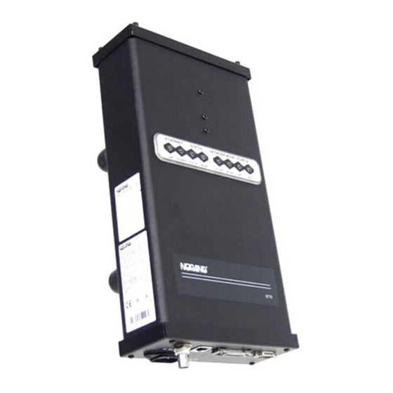
" " " " " " " " " " STATUS NETWORK MODE POLARITY STATUS MODE R-LINK Figure 6-1 Indicator Lights 6710 Access Point User’s Guide Section 6 " " " " " " " " PCMCIA W-LINK NIC1 NIC2... -
Page 194: Ethernet Lights
ON and OFF. Light LINK POLARITY STATUS Lights STATUS indicator lights are labeled STATUS and MODE. 6710 Access Point User’s Guide Indicator Lights LINK and POLARITY STATUS and MODE R-LINK and W-LINK NIC1 and NIC2 Table 6-1... -
Page 195: Table 6-2 Error Mode Status Codes
STATUS The STATUS (left) light indicates the access point’s operating status. When the light is OFF, the access point is operating normally. When the light is ON, it is in error mode. " NOTE: In certain cases the following text refers to the indicator lights by number. -
Page 196: Mode
Timer test failed MODE The right STATUS light is labeled MODE. It indicates the current status of the access point (Table 6-3). 6710 Access Point User’s Guide Description These errors indicate an internal hard- ware error or malfunction. The errors can occur when you apply power to the access point. -
Page 197: Network Mode Lights
Unit is attached to the network through an RF (radio) connection. Unit is operating as the super root. Unit is attached to network through an RF connection and is the designated bridge for a secondary Ethernet LAN. 6710 Access Point User’s Guide Indicator Lights "... -
Page 198: Pcmcia Lights
— the DIAG port’s baud rate. The lights show the status about eight seconds after the W-LINK light stops blinking. Table 6-6 shows baud rates. R-LINK W-LINK 6710 Access Point User’s Guide Table 6-5 PCMCIA Indicator Lights Table 6-6 DIAG Port Baud Rates, ROM Mode... -
Page 199: Power-Up Sequence
Power-Up Sequence When you power on the access point, it performs a power-up sequence that does the following: Tests the indicator lights. " Tests the functional circuits. " Determines the operational status. " Determines the boot sequence. " You can monitor the power-up sequence through the indicator lights. - Page 200 SECTION 6 Indicator Lights " 6710 Access Point User’s Guide...
-
Page 201: Product Specifications
Two PC-card--compatible slots Autosensing 100, 110, 220, 240 V ac 50 to 60 Hz UL/CSA (Underwriters Laboratory/ Canadian Standards Association), United States and Canada; CB (Competent Body) report for Europe 6710 Access Point User’s Guide Appendix A " " " " "... -
Page 202: Appendix A Access Point Specifications
Appendixes B, C, and D, respectively. Physical Characteristics Approximate size: Approximate weight: 6710 Access Point User’s Guide EN (Euro Norm) 50082-1 Generic Immunity Standard and ETS (European Telecommunica- tion Standard) 300--339 Radio Equipment and Systems; Generic EMC (Electromagnetic Com-... -
Page 203: Wlif Specifications And Antennas
Up to 500 feet line of sight 25,000 square feet (2,322 square meters) in typical indoor installations 800 Kbps or 1.6 Mbps, manual or autoselecting Requires communications driver included with the 6710 Access Point software addressing 100 mW RangeLAN2 6710 Access Point User’s Guide Appendix B "... -
Page 204: Radio Operation
245-149-100 219-008-001 (for PC card slot 1 or 2) 245-149-105 219-009-001 (for PC card slot 1 or 2) 6710 Access Point User’s Guide F to 122 F (--20 C to 50 Industry Canada RSS 210 European Union ETS 300-328 CE EMC-EEC in Europe... -
Page 205: Antenna Regulations
Remote antenna kits allow a variety of antenna configurations (for a radio installed in the access point) to be located up to 30 feet from the access point. All remote antenna kits include a mounting bracket. Contact your Sales Representative for information about the antenna kit most suitable for your installation. -
Page 206: Medium Gain Collinear Dipole
This antenna should only be used when it can reduce the number of access points in the system. The following chart lists kit part numbers. Cable Length 10 feet 20 feet 30 feet 6710 Access Point User’s Guide Kit Part Number 203-423-001 203-423-002 203-423-003 Kit Part Number 203-423-004... -
Page 207: High Gain Yagi
30 feet Antenna Adapter Cable The antenna adapter cable (Figure B-1) enables INTERMEC the 6710 Access Point. The cable’s part number is 226-295-001. Consult your Sales Representative for the regulatory status and availability of this part outside of North America. -
Page 208: Model 2100 Antennas And Cables
3 dBi omni 9 dBi omni 3 dBi mini omni 5 dBi dual flat 9 dBi flat panel 6710 adapter cable (to cable) (page B-5) Cable, 2.5 feet (76 cm) Cable, 5 feet (152 cm) Cable, 20 feet (610 cm) Splitter... -
Page 209: Rm160
90, 225, or 450 Kbps (depends on installation) 7 @ 90 Kbps, 1 @ 225 or 450 Kbps Requires communications driver included with the 6710 Access Point software 250 mW Open wireless LAN MAC radio proto- F to 122... -
Page 210: Mhz Specifications And Antennas
Antenna Regulations For 900 MHz systems, regulations require the antenna and antenna connector on the access point to be unique and not commercially available. This ensures that the RF output of the radio stays within the limits specified by the regulating agencies. -
Page 211: Remote Antenna Kits
Remote antenna kits allow a variety of antenna configurations (for a radio installed in the access point) to be located up to 30 feet from the access point. Contact your Sales Representative for information about the antenna kit most suitable for your installation. - Page 212 APPENDIX C 900 MHz Specifications and Antennas " 6710 Access Point User’s Guide...
-
Page 213: Rm111
20 kHz or 25 kHz 27 dBm (.5 Watts) --105 dBm 500 mW Open wireless LAN MAC radio protocol F to 122 F (--20 6710 Access Point User’s Guide Appendix D " " " " " " "... -
Page 214: Appendix D S-Uhf Specifications And Antennas
Part Number 245-149-102 219-006-001 (PC card slot 2 only) 219-007-001 (low band) (PC card slot 2 only) 6710 Access Point User’s Guide ETS 300-220 CE 300-339 (Europe) MPT 1329 FTZ 2014 Consult a local sales office for the cur- rent regulatory status. -
Page 215: Antenna Connector
The following chart lists cabled external whip antennas. Length 5 feet 18 feet 36 feet 50 feet 75 feet 100 feet APPENDIX D S-UHF Specifications and Antennas " Part Number 203-449-002 203-449-003 203-449-001 203-449-004 203-449-005 203-449-006 6710 Access Point User’s Guide... -
Page 216: Site License
Consult your Sales Representative for more information. Transaction Rates S-UHF performance is sensitive to transaction rate and terminal count. The installation guideline is 32 or fewer wireless stations per frequency. The following chart shows guidelines for multiple frequency installations. 6710 Access Point User’s Guide... -
Page 217: Installation Guidelines
** Reflects typical expected coverage for industrial and ware- housing applications. APPENDIX D S-UHF Specifications and Antennas " # Wireless Stations Table D-1 Coverage Prediction Þ Þ 120K* 100K 100K 84K** ß 68K** ß ß 6710 Access Point User’s Guide Þ 64K** 52K** 34K*... -
Page 218: Installing A Single Access Point
Extending Coverage Multiple access points may be installed to extend coverage. Figure D-1 shows an installation where maximizing coverage is the main objective. " NOTE: A site survey is required for this type of installation. 6710 Access Point User’s Guide... -
Page 219: Reusing The Frequency
Reusing the Frequency If access points are separated by sufficient distance, you can reuse a frequency, as illustrated in Figure D-2. 6710 Access Point User’s Guide... -
Page 220: Increasing System Throughput
100 stations, and three transactions per second. Large wireless station populations or transaction rates require use of one of the high speed RF media. 6710 Access Point User’s Guide - - 105 dBm Access Point B Figure D-2... -
Page 221: Option 1
Option 2 Option 2 is recommended if the coverage area is small enough that all access points can be installed to cover the full area. See Figure D-3. S-UHF Specifications and Antennas 6710 Access Point User’s Guide... -
Page 222: Frequency And Separation Guidelines
Absolute minimum separations are based on frequency separation, as indicated in the following chart. Frequency Separation 50 KHz ³ 200 KHz D-10 6710 Access Point User’s Guide 60 wireless stations maxi- mum in overlap area (two frequencies) 100 wireless stations maximum in overlap area (four frequencies) -
Page 223: Introduction
Support of wireless stations using both IP and " ordinarily nonroutable protocols. " " " " " " " " " " 6710 Access Point User’s Guide Appendix E OWL/IP " " " " " " " "... -
Page 224: Appendix E Owl/Ip
" OWL/IP is activated by enabling the OWL/IP port in the access point. The port is an entryway to an IP tunnel originated by the super root on the home subnet, and terminated by a designated bridge operating on a remote subnet. -
Page 225: Owl/Ip Safeguards
IP address resolution, and ICMP, which supports diagnostic capabilities such as PING. Extensive filtering capabilities are provided to allow traffic to be restricted to that known to be destined to wireless stations. APPENDIX E OWL/IP " 6710 Access Point User’s Guide... -
Page 226: Addressing Limitations And Flooding Restrictions
MAC frames used for coordinating bridges. These frames are not forwarded: 802.1d bridge frames. " IP frames with a broadcast or multicast Ethernet " address. IP frames with the following (router) protocol types " and decimal values: 6710 Access Point User’s Guide... - Page 227 BGP (179) (Border Gateway Protocol) RAP (38) (Route Access Protocol) These frames are always forwarded: DIX 0875C open wireless LAN inter-access point " coordination frames DIX 0800 Internet Protocol " IP Protocol (47) GRE " APPENDIX E OWL/IP " 6710 Access Point User’s Guide...
-
Page 228: Default Filter Settings
OWL/IP automatically provides subnet filtering for IP wireless stations. Designated bridges never forward frames to the home subnet, unless the IP address belongs to the home subnet. This feature prevents inbound flooding of undesired IP traffic. 6710 Access Point User’s Guide... -
Page 229: Password Security
Frames to or from a secondary Ethernet LAN are bridged at the MAC layer. In the case of OWL/IP, a virtual MAC layer link is established through an “IP tunnel” between the super root and a designated bridge. 6710 Access Point User’s Guide... - Page 230 Wireless Station AP 3 (Designated AP 4 AP 5 Bridge) Secondary LAN Remote Subnet Wireless Station Wireless Station 6710 Access Point User’s Guide Wireless Link AP 1 Figure E-1 Secondary LAN AP 1 (Super Root) IP Network IP Router IP Router...
-
Page 231: Tunnel Origination
At power up, all super root candidates listen for hello messages. If they do not detect hellos, or detect hellos from a lower priority root candidate, they begin to send hello messages. APPENDIX E OWL/IP " 6710 Access Point User’s Guide... -
Page 232: Establishing And Maintaining Tunnels
The number of remote subnets and redundancy needs on each subnet influences the selection of address types in the [IP Addresses] menu. See the configuration examples on page E-13. E-10 6710 Access Point User’s Guide... -
Page 233: Frame Forwarding
Frames destined for servers or stations on the local subnet are not forwarded through tunnels. Only frame types configured in the [TX Filter] menu are forwarded. 6710 Access Point User’s Guide APPENDIX E OWL/IP " E-11... -
Page 234: Station Mobility
OWL/IP is designed primarily to operate in local area environments, where handcarried or vehicle mounted stations may move rapidly between access point coverage areas on a subnetted LAN. The two technologies are complimentary and may coexist. Table E-1 summarizes some differences. E-12 6710 Access Point User’s Guide... -
Page 235: Owl/Ip Configuration Examples
Is a standard feature in open wireless LAN system soft- ware. 6710 Access Point User’s Guide OWL/IP " E-13... - Page 236 IP Router AP 4 (Designated Bridge) 192.168.17.16 IP Station NNL Station 192.168.15.227 Subnet Mask: 255.255.255.0 Example Class C Configuration E-14 6710 Access Point User’s Guide AP 1 Server for (Super Root) IP Stations 192.168.15.101 192.168.15.17 192.168.15.1 Home Subnet AP 2 Server for 192.168.15.36...
-
Page 237: Step
AP 5 is chosen as the designated bridge for subnet " 192.168.23.21. Step 3 The two super root candidates are configured to originate tunnels. Two options are available: unicast addressing and directed broadcast. 6710 Access Point User’s Guide APPENDIX E OWL/IP " E-15... -
Page 238: Option A: Unicast Addressing
The access point with the highest bridge priority provides the remote termination of the OWL/IP tunnel. A broadcast MAC address is used. Following is the IP Addresses Table for this option: E-16 6710 Access Point User’s Guide Type Address 1 <Unicast> 192.168.17.16 2 <Unicast>... -
Page 239: Step 4: Set Tx Filters
TCP or UDP can be enabled by changing the DIX TCP and DIX UDP ports to pass all frames. Following is the [Frame Types] screen: DIX-IP-TCP Ports DIX-IP-UDP Ports 6710 Access Point User’s Guide APPENDIX E OWL/IP " Address 192.168.17.255... - Page 240 “20.” Values are displayed in the table as hexadecimal values: 14, 15, and 17. Following is the [SubTypes 1] screen: DIX-ARP SNAP-ARP 802.2-IPX-RIP 802.2-IPX-SAP NETBIOS E-18 6710 Access Point User’s Guide Action Scope <Drop> <Unlisted> <Drop> <Unlisted> Action SubType <Pass>...
-
Page 241: Example 2: Class B Ip Address Using Subnetting
Other access points on the subnet are configured with " bridge priority 0. AP 21 and AP 22, AP 31 and AP 32, etc. are configured " as designated bridge candidates for their respective subnets. 6710 Access Point User’s Guide APPENDIX E OWL/IP " E-19... - Page 242 172.16.40.2 172.16.8.3 172.16.40.1 IP Router AP 31 172.16.48.2 172.16.8.4 172.16.48.1 IP Router Example Class B Configuration E-20 6710 Access Point User’s Guide Server for Server for IP Stations NNL Stations 172.16.23.141 Home Subnet AP 12 AP 13 172.16.32.3 172.16.32.4 AP 22 AP 23 172.16.40.3...
-
Page 243: Option B: Directed Broadcast
OWL/IP tunnel for each subnet. A broadcast MAC address is used. This option supports primary and fallback access points on up to eight subnets. 6710 Access Point User’s Guide APPENDIX E OWL/IP "... -
Page 244: Option C: All Subnets Broadcast
See Comments on the next page before using the All Subnets broadcast. Directed broadcast is the preferred implementation for larger system installations. E-22 6710 Access Point User’s Guide Type Address 1 <Broadcast> 172.16.23.255 2 <Broadcast>... -
Page 245: Step
Consult your Sales Representative or Technical Support for more information. Step 4 TX filter set up is identical to Example 1 (page E-13). 6710 Access Point User’s Guide APPENDIX E OWL/IP " E-23... - Page 246 APPENDIX E OWL/IP " E-24 6710 Access Point User’s Guide...
-
Page 247: Port And Cable Pin-Outs
" " " " This appendix lists pin-outs for the 6710 Access Point’s DIAG and AUI ports, and the standard null modem cable. DIAG Port Pin-Outs The following chart defines the signals present on the pins for the DIAG port. Pin numbering is from left to right and top to bottom. -
Page 248: Aui Port Pin-Outs
AUI port. Pin numbering is from left to right and top to bottom. For example, pin 1 is on the top left of the connector, and the last pin is on the bottom right. Pin Number 6710 Access Point User’s Guide Signal Name Data Data... -
Page 249: Diag Port Cable
9-pin, D-sub Female APPENDIX F Port and Cable Pin-Outs " DIAG Port to 9-pin Male PC Port Part Number: 226-106-001 (6 feet) 6710 SHELL GND 6710 Access Point User’s Guide Pin 1 Pin 6 Pin 9 Pin 5 9-pin, D-sub Female... - Page 250 APPENDIX F Port and Cable Pin-Outs " 6710 Access Point User’s Guide...
-
Page 251: Product Contents
" " " " Product Contents The 6710 Access Point MIB is on disk part number 215-894-001. Order the MIB through your Sales Representative. The following products are available for management of the open wireless LAN/INCA LAN: HP OpenView for Windows "... -
Page 252: Appendix G Mib
APPENDIX G " These MIBs are on the 6710 Access Point’s MIB disk. You need to load the MIBs onto your management platform to query the access point for these management objects. Getting Started Install the MIBs onto your management platform in this order: 1. -
Page 253: Access Point Mib Information
1.3.6.1.2.1.11 Allows data to be collected about SNMP devices * The 6710 Access Point does not support EGP and CMOT. 6710 Access Point MIB Information Intermec has structured its proprietary management information similar to MIB-II. In addition to MIB-II, the 6710 Access Point supports information specific to its operation. -
Page 254: Access To Management Information
1.3.6.1.4.1.469.1000.2.17 nControl 1.3.6.1.4.1.469.1000.2.105 Device control Access to Management Information Access to Intermec management information is obtained with the proper COMMUNITY name. Intermec provides three levels of access. This table outlines the levels with the required community name. 6710 Access Point User’s Guide... - Page 255 SUPER-USER community definition. This record is not removable. This is a fixed record to ensure read-write access to the MIBs on the 6710 Access Point. Note the communityName for the first record can be changed to ensure end-user control of security for the 6710 Access Point.
-
Page 256: Mib-Ii Notes
System Group Interfaces Group IP Forwarding MIB Directory The following pages describe the various groups the 6710 Access Point supports. Table G-3 lists groups, their meaning, and page numbers where each group’s table summary and definitions appear. 6710 Access Point User’s Guide Three fields in the MIB-II system group are writable. -
Page 257: Product Oids
G-10 G-10 G-11 G-11 G-12 G-13 G-14 G-15 G-16 G-17 G-17 G-18 G-19 G-20 G-20 G-22 G-23 G-23 6710 Access Point User’s Guide " Definition G-24 G-24 G-25 G-26 G-28 G-30 G-32 G-36 G-41 G-46 G-49 G-52 G-55 G-56 G-61... -
Page 258: Mib Outline
This group contains an Object IDentification (OID) for each INTERMEC device. Object Name ap6710 gw4030 wnas ts6950 gwap6910 uap2100 msd6710 6710 Access Point User’s Guide Table G-4 products GROUP Device Products norand.manage.products.x (1.3.6.1.4.1.469.1000.1.x) Object Type Access OBJECT ID Not Applicable (N/A) OBJECT ID... -
Page 259: Table G-5 Hw Group
File Segment Information (page G-26) Software Directory Listing (page G-28) Critical Errors Information (page G-30) Table G-5 hw GROUP Device Hardware Information (1.3.6.1.4.1.469.1000.2.1.1.x) Object Type INTEGER DisplayString read INTEGER INTEGER INTEGER 6710 Access Point User’s Guide " Access read read read read... -
Page 260: Table G-6 Fsinfo Group
Object Name 2.1.1 segID 2.1.2 segFirstSector 2.1.3 segLastSector 2.1.4 segStatus 2.1.5 segSize 2.1.6 segFree G-10 6710 Access Point User’s Guide Table G-6 fsinfo GROUP Device File System Information (1.3.6.1.4.1.469.1000.2.1.3.1.x) Object Type Access INTEGER INTEGER INTEGER INTEGER Gauge INTEGER INTEGER Table G-7... -
Page 261: Table G-8 Dir Group
Table G-9 criticalErrors GROUP Device Critical Errors Information norand.manage.norandNet.nSystem.sysErrors.criticalErrors.x (1.3.6.1.4.1.469.1000.2.1.4.1.x) Object Name ceEnabled ceOverflow ceReset 4.1.1 ceLogErrorCode 4.1.2 ceLogErrorCount 6710 Access Point User’s Guide APPENDIX G " Object Type Access INTEGER read DisplayString read INTEGER read INTEGER read INTEGER read... -
Page 262: Table G-10 Nifx Group
4.1.9 nifxExcessiveDeferrals 4.1.10 nifxInNetIDDiscards 4.1.11 nifxInFragDiscards 4.1.12 nifxInUFilterDiscards 4.1.13 nifxInNUFilterDiscards 4.1.14 nifxInQFullDiscards G-12 6710 Access Point User’s Guide Norand Extensions to Interfaces Table (page G-32) Port Transmit Queue (page G-46) Pending Message Services (page G-49) Table G-10 nifx GROUP (1.3.6.1.4.1.469.1000.2.2.2.x) -
Page 263: Table G-11 Portstate Group
4.1.9 psMacdWindow 4.1.10 psMacdQSize 4.1.11 psMacdTimeouts 4.1.12 psIsPrimary 4.1.13 psIsSecondary 4.1.14 psIsSecondaryCandidate 4.1.15 psSecondaryUniFlooding 4.1.16 psSecondaryMultiFlooding 4.1.17 psIsRadio 4.1.18 psPendEnabled 6710 Access Point User’s Guide APPENDIX G " Object Type Access INTEGER read INTEGER read PhysAddress read INTEGER read INTEGER... -
Page 264: Table G-12 Portstats Group
4.1.16 pstcInUcastInbound 4.1.17 pstcInUcastOutbound 4.1.18 pstcInUcastSec 4.1.19 pstcInUcastFlood 4.1.20 pstcUcastDiscards 4.1.21 pstcInNUcastDiscards 4.1.22 pstcInUcastToIFC 4.1.23 pstcInNUcastToIFC 4.1.24 pstcOutDelayDiscards G-14 6710 Access Point User’s Guide Table G-12 portStats GROUP Device Port Statistics (1.3.6.1.4.1.469.1000.2.2.4.x) Object Type Access INTEGER Counter Counter Counter Counter... -
Page 265: Table G-13 Ptxq Group
1.1.6 ptxqQHpCount 1.1.7 ptxqQExpCount 1.1.8 ptxqQRegCount 1.1.9 ptxqQHpDiscards 1.1.10 ptxqQExpDiscards 1.1.11 ptxqQRegDiscards 1.1.12 ptxqMultiQSize 1.1.13 ptxqMultiQMax 1.1.14 ptxqMultiQDiscards 6710 Access Point User’s Guide APPENDIX G " Object Type Access INTEGER read Gauge read INTEGER read Gauge read INTEGER read... -
Page 266: Table G-14 Pmsg Group
1.1.5 pmsgPendMsgMax 1.1.6 pmsgPendMsgTotal 1.1.7 pmsgPendMsgDiscards 1.1.8 pmsgPendRecOverflowErrors 1.1.9 pmsgPendMsgOverflowErrors 1.1.10 pmsgPendAgedRecCount 1.1.11 pmsgPendAgedMsgCount G-16 6710 Access Point User’s Guide Table G-14 pmsg GROUP Device Pending Message Service (1.3.6.1.4.1.469.1000.2.2.6.x) Object Type Access INTEGER Gauge INTEGER Gauge INTEGER Counter Counter Counter... -
Page 267: Snmp Version 1 Configuration Group
Device SNMP v1 Configurations (1.3.6.1.4.1.469.1000.2.11.1.x) Object Type INTEGER INTEGER DisplayString write INTEGER Table G-16 trapTarget TABLE Device SNMP v1 Configurations (1.3.6.1.4.1.469.1000.2.11.1.x) Object Type INTEGER INTEGER DisplayString write IpAddress 6710 Access Point User’s Guide " Access read write write Access read write write G-17... -
Page 268: Table G-17 Rt Group
2.1.6 rtAttachTime 2.1.7 rtApEaddr 2.1.8 rtHopAddrLen 2.1.9 rtHopAddr16 G-18 6710 Access Point User’s Guide Route Table (page G-56) Bridge Table (page G-61) Address Table (page G-63) Bridge State Information (page G-64) Table G-17 rt GROUP Device Route Table (1.3.6.1.4.1.469.1000.2.17.2.x) Object Type Access... -
Page 269: Table G-18 Brg Group
Device Bridge Table norand.manage.norandNet.nBridge.brg.x (1.3.6.1.4.1.469.1000.2.17.3.x) Object Name 2.1.1 brgDestination 2.1.2 brgPort 2.1.3 brgAge 2.1.4 brgType 2.1.5 brgIsPermanent 2.1.6 brgTimestamp 6710 Access Point User’s Guide APPENDIX G " Object Type Access PhysAddress read INTEGER read INTEGER read INTEGER read INTEGER read INTEGER read... -
Page 270: Table G-19 Addr Group
2.1.6 addrIpAddress norand.manage.norandNet.nBridge.brgState.x Object Name bsAddress bsLanId bsCostToRoot bsIsRoot bsIsAttached bsAttachId bsMyRootPriority bsRootPort G-20 6710 Access Point User’s Guide Table G-19 addr GROUP Address Table (1.3.6.1.4.1.469.1000.2.17.4.x) Object Type PhysAddress INTEGER INTEGER DisplayString read INTEGER IPAddress Table G-20 brgState GROUP Bridge State Information (1.3.6.1.4.1.469.1000.2.17.6.x) - Page 271 6710 Access Point User’s Guide APPENDIX G " Object Type Access PhysAddress read INTEGER read INTEGER read PhysAddress read INTEGER read INTEGER read Counter...
-
Page 272: Control Groups
Control Groups Objects in the following groups exert control over the 6710 Access Point. Present functions include rebooting and scheduling software downloads. " NOTE: The MIB definition for each group starts on the page given below. -
Page 273: Mib Definitions
Object Name sdStartTime sdServerIpAddress sdScriptFilename sdStatus sdErrorString sdCheckPoint sdSetActivePointers sdTerminate MIB Definitions Following are the MIB definitions for the 6710 Access Point. APPENDIX G Table G-22 powerUp GROUP Device Power Up Objects (1.3.6.1.4.1.469.1000.2.105.1.x) Object Type Access Counter TimeTicks Table G-23... - Page 274 DESCRIPTION ”The description of the hardware device.” ::= { hw 2 } G-24 6710 Access Point User’s Guide OBJECT IDENTIFIER ::= { enterprises 469 } OBJECT IDENTIFIER ::= { norand 1000 } OBJECT IDENTIFIER ::= { manage 1 } OBJECT IDENTIFIER ::= { products 1 }...
- Page 275 DESCRIPTION ”The device identifier of the hardware device. Values = 3250, 4000, 4020, 4030, 4033, 3240, 1000, 1100, 1700, 5940, 4650, 100 (ACE process), 200 (DOSNMS), 300 (Norand Proxy Agent), 6710 (Access Point).” ::= { hw 5 } file OBJECT IDENTIFIER ::= { nSystem 3 }...
- Page 276 ::= { fsinfo 7 } segment -- The File Segment Table -- Table Definition G-26 6710 Access Point User’s Guide OBJECT-TYPE OBJECT-TYPE OBJECT IDENTIFIER ::= { file 2 } If the Files...
- Page 277 ::= { segEntry 1 } segFirstSector OBJECT-TYPE SYNTAX INTEGER ACCESS read-only STATUS mandatory DESCRIPTION ”The first physical sector in the segment (1 - (MAX_SECTORS + 1))” ::= { segEntry 2 } 6710 Access Point User’s Guide APPENDIX G " G-27...
- Page 278 SYNTAX SEQUENCE OF DIREntry ACCESS not-accessible STATUS mandatory DESCRIPTION ”The FileSystem Directory” ::= { dir 2 } -- Row Definition G-28 6710 Access Point User’s Guide OBJECT-TYPE OBJECT-TYPE valid(1), invalid(2) } valid = 1, invalid = 2 ” OBJECT-TYPE...
- Page 279 OBJECT-TYPE SYNTAX INTEGER ACCESS read-only STATUS mandatory DESCRIPTION ”File segment (1 - (NUM_SEGMENTS + 1)). The segment ID which identifies the segment containing the file.” ::= { dirEntry 3 } 6710 Access Point User’s Guide APPENDIX G " G-29...
- Page 280 STATUS mandatory DESCRIPTION ”The file version in v99.99 display format.” ::= { dirEntry 8 } sysErrors criticalErrors OBJECT IDENTIFIER ::= { sysErrors 1 } G-30 6710 Access Point User’s Guide OBJECT-TYPE data(2), invalid(3) } executable = 1, data = 2, invalid = 3 ”...
- Page 281 ”Critical Error Log Table” ::= { criticalErrors 4 } ceLogEntry OBJECT-TYPE SYNTAX CELogEntry ACCESS not-accessible STATUS mandatory INDEX { ceLogErrorCode } ::= { ceLogTable 1 } 6710 Access Point User’s Guide APPENDIX G " Any errors in that Valid values are G-31...
- Page 282 SYNTAX NIFXEntry ACCESS not-accessible STATUS mandatory INDEX { nifxIndex } ::= { nifxTable 1 } G-32 6710 Access Point User’s Guide INTEGER, OBJECT-TYPE A 16-bit value which OBJECT IDENTIFIER ::= { norandNET 2 } OBJECT IDENTIFIER ::= { nInterfaces 2 }...
- Page 283 SYNTAX INTEGER { ether(4), bb485(33), owlIP(66), proxim24(132), nor24(195), falcon902(197), uhf(198) ACCESS read-only STATUS mandatory DESCRIPTION ”Norand Interface Type” ::={ nifxEntry 2 } 6710 Access Point User’s Guide APPENDIX G " INTEGER, INTEGER, Counter, Counter, Counter, Counter, Counter, Counter, Counter, Counter,...
- Page 284 ::={ nifxEntry 6 } nifxInNUcastDPkts SYNTAX Counter ACCESS read-only STATUS mandatory DESCRIPTION ”The number of received multicast frames successfully delivered to the MAC-D task” ::={ nifxEntry 7 } G-34 6710 Access Point User’s Guide Unicast ethernet frames are OBJECT-TYPE OBJECT-TYPE OBJECT-TYPE OBJECT-TYPE...
- Page 285 ::={ nifxEntry 11 } nifxInUFilterDiscards OBJECT-TYPE SYNTAX Counter ACCESS read-only STATUS mandatory DESCRIPTION ”The number of enabled received unicast frames discarded due to a unicast filter expression” ::={ nifxEntry 12 } 6710 Access Point User’s Guide APPENDIX G " G-35...
- Page 286 ”MAC-R port state variables” ::= { portState 4 } psEntry SYNTAX PSEntry ACCESS not-accessible STATUS mandatory INDEX { psPort } ::= { psTable 1 } G-36 6710 Access Point User’s Guide OBJECT-TYPE OBJECT IDENTIFIER ::= { nInterfaces 3 } OBJECT-TYPE OBJECT-TYPE...
- Page 287 ::= { psEntry psAddress OBJECT-TYPE SYNTAX PhysAddress ACCESS read-only STATUS mandatory DESCRIPTION ”802 address of the port” ::= { psEntry 6710 Access Point User’s Guide APPENDIX G " INTEGER, INTEGER, PhysAddress, INTEGER, INTEGER, INTEGER, INTEGER, Counter,...
- Page 288 SYNTAX INTEGER ACCESS read-only STATUS mandatory DESCRIPTION ”Incremental path cost of the port. Default values: ether Falcon = 100, ::= { psEntry G-38 6710 Access Point User’s Guide OBJECT-TYPE ether(4), bb485(33), owlIP(66), proxim24(132), nor24(195), falcon902(197), uhf(198) = 4, = 198”...
- Page 289 ”MAC-D transmit timeout errors” ::= { psEntry 11 } psIsPrimary OBJECT-TYPE SYNTAX INTEGER { true(1), false(2) } ACCESS read-only STATUS mandatory DESCRIPTION ”TRUE, for primary bridge ports” ::= { psEntry 12 } 6710 Access Point User’s Guide APPENDIX G " G-39...
- Page 290 ::= { psEntry 17 } psPendEnabled SYNTAX INTEGER { true(1), false(2) } ACCESS read-only STATUS mandatory DESCRIPTION ”TRUE, if the port supports pending messages” ::= { psEntry 18 } G-40 6710 Access Point User’s Guide OBJECT-TYPE OBJECT-TYPE OBJECT-TYPE OBJECT-TYPE OBJECT-TYPE...
- Page 291 APPENDIX G " OBJECT-TYPE OBJECT-TYPE INTEGER, Counter, Counter, Counter, Counter, Counter, Counter, Counter, Counter, Counter, Counter, Counter, Counter, Counter, Counter, Counter, Counter, Counter, Counter, Counter, Counter, Counter, Counter, Counter 6710 Access Point User’s Guide G-41...
- Page 292 ”Received OWL packets with errors” ::= { pstcEntry 5 } pstcOutOWLPkts SYNTAX Counter ACCESS read-only STATUS mandatory DESCRIPTION ”Total OWL packets sent” ::= { pstcEntry 6 } G-42 6710 Access Point User’s Guide OBJECT-TYPE A number which uniquely OBJECT-TYPE OBJECT-TYPE OBJECT-TYPE OBJECT-TYPE OBJECT-TYPE...
- Page 293 STATUS mandatory DESCRIPTION ”Link errors which generated an ALERT” ::= { pstcEntry 11 } pstcInUcastRelayPkts OBJECT-TYPE SYNTAX Counter ACCESS read-only STATUS mandatory DESCRIPTION ”Received unicast relay packets” ::= { pstcEntry 12 } 6710 Access Point User’s Guide APPENDIX G " G-43...
- Page 294 ”Received unicast data packets routed outbound” ::= { pstcEntry 17 } pstcInUcastSec SYNTAX Counter ACCESS read-only STATUS mandatory DESCRIPTION ”Received unicast data packets relayed to a secondary LAN” ::= { pstcEntry 18 } G-44 6710 Access Point User’s Guide OBJECT-TYPE OBJECT-TYPE OBJECT-TYPE OBJECT-TYPE OBJECT-TYPE OBJECT-TYPE...
- Page 295 ”Received multicast packets passed to the data link interface” ::= { pstcEntry 23 } pstcOutDelayDiscards OBJECT-TYPE SYNTAX Counter ACCESS read-only STATUS mandatory DESCRIPTION ”Send packets discarded due to excessive delay” ::= { pstcEntry 24 } 6710 Access Point User’s Guide APPENDIX G " G-45...
- Page 296 ACCESS read-only STATUS mandatory DESCRIPTION ”MAC-R port ID (1-4). A number which uniquely indentifies the port.” ::= { ptxqEntry 1 } G-46 6710 Access Point User’s Guide OBJECT IDENTIFIER ::= { nInterfaces 5 } OBJECT-TYPE OBJECT-TYPE INTEGER, Gauge, INTEGER, Gauge,...
- Page 297 ::= { ptxqEntry 5 } ptxqQHpCount OBJECT-TYPE SYNTAX Counter ACCESS read-only STATUS mandatory DESCRIPTION ”The number of attempts to queue a high priority packet for transmission” ::= { ptxqEntry 6 } 6710 Access Point User’s Guide APPENDIX G " G-47...
- Page 298 ::= { ptxqEntry 10 } ptxqQRegDiscards SYNTAX Counter ACCESS read-only STATUS mandatory DESCRIPTION ”The number of failed attemts to queue a regular priority packet” ::= { ptxqEntry 11 } G-48 6710 Access Point User’s Guide OBJECT-TYPE OBJECT-TYPE OBJECT-TYPE OBJECT-TYPE OBJECT-TYPE...
- Page 299 ”Pending Message Table” ::= { pmsg 1 } pmsgEntry SYNTAX PmsgEntry ACCESS not-accessible STATUS mandatory INDEX { pmsgPort } ::= { pmsgTable 1 } APPENDIX G " The number of Multicast packets are OBJECT-TYPE OBJECT-TYPE 6710 Access Point User’s Guide G-49...
- Page 300 ”Maximum terminal record count” ::= { pmsgEntry 3 } pmsgPendMsgCurrent SYNTAX Gauge ACCESS read-only STATUS mandatory DESCRIPTION ”Current pending message count” ::= { pmsgEntry 4 } G-50 6710 Access Point User’s Guide INTEGER, Gauge, INTEGER, Gauge, INTEGER, Counter, Counter, Counter, Counter...
- Page 301 ::= { pmsgEntry 8 } pmsgPendMsgOverflowErrors OBJECT-TYPE SYNTAX Counter ACCESS read-only STATUS mandatory DESCRIPTION ”The number of times when the maximum number of stored messages, per platform, was exceeded.” ::= { pmsgEntry 9 } 6710 Access Point User’s Guide APPENDIX G " G-51...
- Page 302 --Norand Community table defines the accepted community --strings and their access privileges -- The Community Table G-52 6710 Access Point User’s Guide OBJECT-TYPE OBJECT-TYPE OBJECT IDENTIFIER ::= { norandNET 11 } OBJECT IDENTIFIER ::= { nSNMP 1 }...
- Page 303 DESCRIPTION ”Each entry relates to a specific community & associates to it access privileges.” INDEX { communityIndex } ::= {communityTable 1 } -- Columnar Object Definition 6710 Access Point User’s Guide APPENDIX G " Norand’s All other rows in G-53...
- Page 304 DESCRIPTION ”The authoritative name for the community. the Norand SUPER-USER community name is employed, a GET from this column yields an access violation.” ::= { communityEntry 3 } G-54 6710 Access Point User’s Guide INTEGER, INTEGER, DisplayString, INTEGER OBJECT-TYPE INTEGER...
- Page 305 IP address & belonging to given community.” INDEX { trapTargetIndex } ::= {trapTargetTable 1 } -- Columnar Object Definition TrapTargetEntry ::= SEQUENCE { trapTargetIndex trapTargetStatus trapTargetName trapTargetIpAddress IpAddress -- Leaf Definition APPENDIX G " INTEGER, INTEGER, DisplayString, 6710 Access Point User’s Guide G-55...
- Page 306 STATUS mandatory DESCRIPTION ”Each entry in this table provides routing information for child nodes which are reachable via a route.” ::= { rt 2 } G-56 6710 Access Point User’s Guide OBJECT-TYPE OBJECT-TYPE INTEGER { enabled(1), disabled(2), deleted(3) } read-write...
- Page 307 ::= { rtEntry 1 } rtPort OBJECT-TYPE SYNTAX INTEGER (1..4) ACCESS read-only STATUS mandatory DESCRIPTION ”The MAC-R port ID (1-4). A number which uniquely identifies the port.” ::= { rtEntry 2 } 6710 Access Point User’s Guide APPENDIX G " G-57...
- Page 308 STATUS mandatory DESCRIPTION ”802 address of AP which is the first hop on the path to the destination” ::= { rtEntry 7 } G-58 6710 Access Point User’s Guide OBJECT-TYPE OBJECT-TYPE A 16-bit OBJECT-TYPE The sequence number is The sequence...
- Page 309 ::= { rtEntry 11 } rtIsRemote OBJECT-TYPE SYNTAX INTEGER { true(1), false(2) } ACCESS read-only STATUS mandatory DESCRIPTION ”True if the destination is a non-OWL node” ::= { rtEntry 12 } 6710 Access Point User’s Guide APPENDIX G " G-59...
- Page 310 STATUS mandatory DESCRIPTION ”MAC-R send sequence number for terminal nodes. 16-bit (0-65535) sequence number of the last OWL data request PDU sent to the destination” ::= { rtEntry 17 } G-60 6710 Access Point User’s Guide OBJECT-TYPE OBJECT-TYPE OBJECT-TYPE OBJECT-TYPE OBJECT-TYPE...
- Page 311 INDEX { brgDestination } ::= { brgTable 1 } -- Columnar Object Definition BRGEntry ::= SEQUENCE { brgDestination PhysAddress, brgPort INTEGER, brgAge INTEGER, brgType INTEGER, brgIsPermanent INTEGER, brgTimestamp TimeTicks -- Leaf Definition APPENDIX G " 6710 Access Point User’s Guide G-61...
- Page 312 SYNTAX INTEGER { true(1), false(2) } ACCESS read-only STATUS mandatory DESCRIPTION ”TRUE, if the entry is permanent.” ::= { brgEntry 5 } G-62 6710 Access Point User’s Guide OBJECT-TYPE OBJECT-TYPE A number which uniquely OBJECT-TYPE OBJECT-TYPE primary(1), secondary(2), outbound(3),...
- Page 313 INDEX { addrDestination } ::= { addrTable 1 } -- Columnar Object Definition AddrEntry ::= SEQUENCE { addrDestination PhysAddress, addrAge INTEGER, addrNodeId INTEGER, addrAlias DisplayString, addrDeviceId INTEGER, addrIpAddress IpAddress -- Leaf Definition APPENDIX G " This 6710 Access Point User’s Guide G-63...
- Page 314 ACCESS read-only STATUS mandatory DESCRIPTION ”32-bit IP address for IP nodes (e.g. APs)” ::= { addrEntry 6 } brgState -- The Bridge State Group G-64 6710 Access Point User’s Guide OBJECT-TYPE OBJECT-TYPE OBJECT-TYPE OBJECT-TYPE OBJECT-TYPE An OWL node can, optionally, OBJECT-TYPE...
- Page 315 OBJECT-TYPE SYNTAX INTEGER (0..65535) ACCESS read-only STATUS mandatory DESCRIPTION ”16-bit (0-65535) ATTACH sequence number. number is incremented each time the AP sends an ATTACH request.” ::= { brgState 8 } 6710 Access Point User’s Guide APPENDIX G " This G-65...
- Page 316 STATUS mandatory DESCRIPTION ”Root sequence of the current root (0-255). sequence number identifies a single instance of the root.” ::= { brgState 13 } G-66 6710 Access Point User’s Guide OBJECT-TYPE An AP with a root The AP OBJECT-TYPE OBJECT-TYPE...
- Page 317 SYNTAX Counter ACCESS read-only STATUS mandatory DESCRIPTION ”Number of times that the AP has changed from an unattached state to an attached state.” ::= { brgState 19 } 6710 Access Point User’s Guide APPENDIX G " The node ID uniquely G-67...
- Page 318 ”Flooding level for unicast frames (1-2)” ::= { brgState 22 } bsMultiFloodLevel SYNTAX INTEGER (0..3) ACCESS read-only STATUS mandatory DESCRIPTION ”Flooding level for multicast frames (0-3)” ::= { brgState 23 } G-68 6710 Access Point User’s Guide OBJECT-TYPE The code indicates the OBJECT-TYPE OBJECT-TYPE OBJECT-TYPE...
- Page 319 OBJECT IDENTIFIER ::= { nBridge 7 } bstcRouteCount SYNTAX Gauge ACCESS read-only STATUS mandatory DESCRIPTION ”Total route table entries” ::= { bridgeStats 3 } APPENDIX G " OBJECT-TYPE OBJECT-TYPE OBJECT-TYPE If the ID is OBJECT-TYPE OBJECT-TYPE 6710 Access Point User’s Guide G-69...
- Page 320 DESCRIPTION ”Inbound bridge table entries” ::= { bridgeStats 8 } bstcSecondaryCount SYNTAX Gauge ACCESS read-only STATUS mandatory DESCRIPTION ”Secondary LAN bridge table entries” ::= { bridgeStats 9 } G-70 6710 Access Point User’s Guide OBJECT-TYPE OBJECT-TYPE OBJECT-TYPE OBJECT-TYPE OBJECT-TYPE OBJECT-TYPE...
- Page 321 ACCESS read-only STATUS mandatory DESCRIPTION ”Out-of-sequence route update errors” ::= { bridgeStats 14 } bstcDeleteSeqErrors OBJECT-TYPE SYNTAX Counter ACCESS read-only STATUS mandatory DESCRIPTION ”Out-of-sequence route delete errors” ::= { bridgeStats 15 } 6710 Access Point User’s Guide APPENDIX G " G-71...
- Page 322 DESCRIPTION ”The amount of time to delay before beginning the software download” ::= { softwareDownLoad 1 } G-72 6710 Access Point User’s Guide OBJECT-TYPE OBJECT IDENTIFIER ::= { norandNET 105 } OBJECT IDENTIFIER ::= { nControl 1 } OBJECT-TYPE OBJECT IDENTIFIER ::= { nControl 2 }...
- Page 323 ”Status of the current software download” ::= { softwareDownLoad 4 } sdErrorString OBJECT-TYPE SYNTAX DisplayString (SIZE (0..40)) ACCESS read-only STATUS mandatory DESCRIPTION ”Description of sdStatus field” ::= { softwareDownLoad 5 } 6710 Access Point User’s Guide APPENDIX G " G-73...
- Page 324 ::= { softwareDownLoad 7 } sdTerminate SYNTAX INTEGER { ACCESS read-write STATUS mandatory DESCRIPTION ”Terminate the current software download” ::= { softwareDownLoad 8 } G-74 6710 Access Point User’s Guide OBJECT-TYPE none(1), boot(2), data(3), both(4) OBJECT-TYPE true(1), false(2)
-
Page 325: Access Point
" " Access Point Access points provide the following functions: A wired bridge is an access point that attaches to the " network through an Ethernet link and has bridging enabled (through access point configuration menus). A wired bridge converts wireless LAN frames to Ethernet frames, and Ethernet frames to wireless LAN frames. - Page 326 Designated Bridge Access points physically connected to a secondary physical LAN, and within the radio coverage area of an access point on the distribution LAN, are candidates to become the des- ignated bridge for the secondary LAN. The designated...
- Page 327 Programmable Read-Only Memory) that can be erased and reprogrammed. Forwarding A frame is forwarded by sending it to the next hop on the path to the final destination. All access points (including wireless access points) forward frames. GLOSSARY 6710 Access Point User’s Guide Glossary-3 "...
- Page 328 Hop is used in vector distance routing and is equal to one data link. A path to the final destination on a net is a se- ries of hops away from the origin. Inbound Frames Frames sent toward the distribution LAN are inbound. Glossary-4 6710 Access Point User’s Guide...
- Page 329 Open Systems Interconnection (OSI) model. Mobile IP Wireless Station In this user’s guide, a mobile IP wireless station is any IP wireless station that can roam across IP subnet boundaries. GLOSSARY computer is an IP wireless 6710 Access Point User’s Guide Glossary-5 "...
- Page 330 The model is a framework of standards used to create protocol stacks and applications for networking applica- tions. Open Wireless LAN Node An open wireless LAN node is any access point or wireless station that connects to the network using the 900 MHz or synthesized UHF radio option. Glossary-6...
- Page 331 Remote Subnet The remote subnet is an Ethernet segment other than the distribution LAN. For Enterprise OWL, the remote subnet is the Ethernet link of the access point that attaches to the super root through an IP tunnel. GLOSSARY 6710 Access Point User’s Guide Glossary-7 "...
- Page 332 The root subnet is the Ethernet segment to which the access point super root connects, which is the distribution LAN. For Enterprise OWL, the root subnet is the Ethernet link of the access point that originates an IP tunnel, which is the super root. Secondary Ethernet LAN A secondary Ethernet LAN is an Ethernet segment that con- nects to the distribution LAN through a wireless link.
- Page 333 LAN spanning tree through its RF port instead of its Ethernet port. The major advantage of using a wireless connection to the LAN is that it reduces, and sometimes even eliminates, the requirements for LAN cabling. GLOSSARY 6710 Access Point User’s Guide Glossary-9 "...
-
Page 334: Wireless Stations
Wireless Stations Wireless stations is an inclusive term that refers to network terminals and wireless computers equipped with wireless NICs. Network terminals include the INTERMEC RT1100 Radio Terminal, RT1700 Radio Terminal, and RT5900 Radio Terminal, and the TRAKKER ANTARES products. Wireless computers include the INTERMEC JANUS, PEN*KEY 6400 Computer, and PEN*KEY 6550 Computer. -
Page 335: Index
C-1 whip antenna, C-2 AC INPUT port, 2-18, 3-20 Access Point Configuration screen, 4-91 Accessories, 2-19 Action, 4-45, 4-53, 4-55 Adding header, 4-41 Address, OWL/IP, 4-83, 4-84 6710 Access Point User’s Guide INDEX " " " " " " "... - Page 336 Cable type, 4-41, 4-42 erasing, 5-8, 5-15, 5-31 Cables, 3-6, 4-3, F-3 finding executable file in, 5-24 mnemonic, 5-3 Callsign, 4-76 Index-2 6710 Access Point User’s Guide Ceiling mount, 3-9 Changing passwords, 4-86 Changing the configuration, 4-13, 4-14 Channel 900 MHz radio, 4-74...
- Page 337 E-4, operation, E-7, E-10 station mobility, E-12 subnet filtering, E-6 terminating tunnel, 4-79, S-UHF radio, 4-57 selection, 4-58 Destination addresses, 2-3, 4-28, 4-37 Destination Unreachable, E-6 DGP, E-5 6710 Access Point User’s Guide INDEX " E-21 E-6, E-11 Index-3...
- Page 338 Electrical specifications, A-1 IP frame type, 4-19 menu option, 4-19, 4-41 Electronic software distribution, OWL frame type, 4-41 Index-4 6710 Access Point User’s Guide Emissions, A-2 Enabled (DHCP), 4-19, 4-20 Enabled, if IP address is zero, 4-19, 4-20 Enabling ARP server mode, 4-36...
- Page 339 4-35, 4-36 definition, Glossary-4 discarding, 4-45, 4-62, 4-63, setting, 4-30, 4-34, 4-35, 4-84 4-36 encapsulating, E-2 flooding inbound, 4-29 to all ports, 4-29 to secondary LANs, 4-29 with unknown destina- 6710 Access Point User’s Guide INDEX " tions, 4-29 Index-5...
- Page 340 HTTP, 2-13, 4-45, 4-89 Guidelines Humidity specifications, A-2 configuration, 4-92 flooding level checklist, 4-31 Hypertext Transfer Protocol, general installation, 3-7 Index-6 6710 Access Point User’s Guide ICMP frequency and separation, IP routing, 4-84 D-10 not filtered, 4-45 installation, D-5 OWL/IP...
- Page 341 4-69 Mask, 4-53, 4-54 Master mode (S-UHF radio), 4-76, 4-77, 4-78 station (WLIF radio) beacon frequency, 4-70 channel, 4-62, 4-67 menu option, 4-60, 4-61 parameters, 4-62 subchannel, 4-62, 4-67 wireless hops, 4-65 6710 Access Point User’s Guide INDEX " Index-7...
- Page 342 Mobile Host Routing Protocol, Ethernet filter, 4-46, 4-51 OWL/IP filter, 4-85, E-18 Mobile IP, E-5, E-12, Glossary-5 NETWORK LIGHT group, 6-2 Index-8 6710 Access Point User’s Guide Network management, 2-14, 3-6 NextPowerUpTime variable, 5-21 NIC1 light, 6-2 NIC2 light, 6-2...
- Page 343 5-25, 5-27 PQ command, 4-5, 5-25, 5-27 Predicting coverage, D-5 4-86 Preparing for installation, 3-2 Primary, 4-29 screen, 4-90 Primary LAN. See Distribution menu, 5-25 Processor, A-1 Product OIDs MIB group, G-7, 6710 Access Point User’s Guide INDEX " Index-9...
- Page 344 E-7 retry, 4-73 redundancy, E-10 fragment QFSK retry, 4-73 restricting frame types, 4-84 Index-10 6710 Access Point User’s Guide Reset Modem Init String com- mand, 5-25, 5-28 Resetting the configuration, 4-13 Resource number, 4-90 Reusing frequencies, D-7...
- Page 345 4-65, 4-66, 4-67 [Slave Parms], 4-60, 4-66 Sname field, 4-20 5-23, 5-24 SNAP example, E-17 filtering, 4-44 header, 4-19, 4-41 SNAP- -ARP Ethernet filter, 4-46, 4-51 OWL/IP filter, 4-85, E-18 SNAP- -EtherType, 4-47, E-18 6710 Access Point User’s Guide INDEX " Index-11...
- Page 346 2-5 [Static Addresses], 4-41, 4-42 Ethernet MAC address, 4-83 Station mobility, E-12 flooding, 4-29, 4-30, 4-59 Index-12 6710 Access Point User’s Guide Super root (Continued) global flooding, 4-28, 4-59 global radio parameters, 4-25 indicator lights, 6-5 OWL/IP filtering, 4-85...
- Page 347 4-81, E-2, E-4 IP addresses, 4-81, E-2, E-4 IP networking, 4-81 LAN ID, 4-24 learning IP addresses of, 4-36 Mobile IP, E-13 mode, 4-75 on different subnets, E-1 6710 Access Point User’s Guide INDEX " frames, 4-33 Index-13...
- Page 348 B-3 specifications, B-1 whip antenna, B-3 Write command, 4-14 Writing the configuration, 4-14 X command, 5-25, 5-28 Yagi antennas, B-5 Ymodem File Download com- mand, 5-23 Ymodem File to PCMCIA com- mand, 5-25, 5-27 Index-14 6710 Access Point User’s Guide...
Need help?
Do you have a question about the 6710 and is the answer not in the manual?
Questions and answers