Table of Contents
Advertisement
Quick Links
Chapter
Radian Video Wall Processor
User Manual
Contact
Information
Page 1
VWP-2040 VWX-2110
VWP-2090 VGC-HDMI-2-4
VWP-2110 VGC-HDMI-2K-4 VCC-HD-4H
VWX-2090 VCC-DP-2
FREE technical support 24 hours a day, 7 days a week:
Call 877-877-2269 or visit blackbox.com
Mailing address: Black Box Corporation, 1000 Park Drive, Lawrence, PA 15055-1018
Web site: www.blackbox.com • E-mail: info@blackbox.com
877-877-2269 | blackbox.com
VCC-HD-4
VCC-SD-HD-3
VCC-HD-4D
VCC-SDI-4
VCC-SDI-SD-HD3
VCC-SD-HD-A-2 VWS-2001
VWS-2002
VWS-2003
Advertisement
Table of Contents

Related Manuals for Black Box Radian VWP-2040


Summary of Contents for Black Box Radian VWP-2040
- Page 1 User Manual FREE technical support 24 hours a day, 7 days a week: Call 877-877-2269 or visit blackbox.com Contact Mailing address: Black Box Corporation, 1000 Park Drive, Lawrence, PA 15055-1018 Information Web site: www.blackbox.com • E-mail: info@blackbox.com 877-877-2269 | blackbox.com...
- Page 2 Trademarks Used in this Manuals Trademarks Used in this Manual Black Box and the Black Box logo type and mark are registered trademarks of Black Box Corporation. ASUS is a registered trademark of Asustek Computer Inc. Intel is a trademark of Intel Corporation or its subsidiaries in the U.S. and/or other countries.
- Page 3 Disclaimer: Black Box Corporation shall not be liable for damages of any kind, including, but not limited to, punitive, consequential or cost of cover damages, resulting from any errors in the product information or specifications set forth in this document and Black Box Corporation may revise this document at any time without notice.
- Page 4 NOM Statement Instrucciones de Seguridad (Normas Oficiales Mexicanas Electrical Safety Statement) 1. Todas las instrucciones de seguridad y operación deberán ser leídas antes de que el aparato eléctrico sea operado. 2. Las instrucciones de seguridad y operación deberán ser guardadas para referencia futura. 3.
- Page 5 Maintenance Only competent technicians should perform maintenance on the Radian Video Wall Processor. Return any Radian Video Wall Processor plug-in cards that are physically damaged to Black Box Corporation. Disposal At the end of life, dispose of all Radian Video Wall Processor products according to local laws and regulations.
- Page 6 4. Click on the “Support” tab on the product page,and select the document you wish to download. If you have any trouble accessing the Black Box site to download the manual, you can contact our Technical Support at 877-877-2269 or info@blackbox.com.
-
Page 7: Table Of Contents
Table of Contents Table of Contents 1. Specifications .................................................10 1.1 Radian Video Wall Processor Chassis, VWP-2040, VWP-2090, VWP-2110 .................10 1.2 Video Graphics Card (VGC-HDMI-2-4): HDMI Graphics Card, Up to 4K Resolution ..........12 1.3 Video Graphics Card (VGC-HDMI-2K-4): HDMI Graphics card, Up to 2K Resolution ..........13 1.4 Video Capture Card (VCC-SD-HD-A-2): (1) HD Channel + (1) SD Channel + AM2 + Cable, Full Height ..14 1.5 Video Capture Card (VCC-SD-HD-3): (2) HD Channels + (1) SD Channel, Full Height ..........15 1.6 Video Capture Card (VCC-SDI-SD-HD-3): (1) HD Channel + (1) HD-SDI Channel + (1) SD Channel,... - Page 8 Table of Contents 5. Software Overview............................................47 5.1 VWS-2001 ..............................................47 5.2 Video Capture Card Software .....................................48 6. Filter Maintenance (VWP-2090 or VWP-2110) .................................50 Appendix A. Installing the Video Graphics Card (VGC-HDMI-2-4 or VGC-HDMI-2K-4) ..............51 A.1 Introduction ..............................................51 A.2 Features ................................................51 A.3 Installing the Video Graphics Card ..................................52 A.3.1 Installing the Display Drivers ..................................53 A.3.2 Installing Additional Video Graphics Cards .............................53 A.4 Video Graphics Card Video BIOS ....................................53...
- Page 9 Table of Contents B.4.4 Installing the Capture Card .....................................81 B.4.5 How to Connect Input Sources ..................................82 B.4.6 Installing Multiple Cards .....................................83 B.4.7 Firmware Upgrades ........................................84 B.5 Video Capture Card (VCC-DP-2) ....................................84 B.5.1 Introduction ...........................................84 B.5.2 Hardware Overview........................................85 B.5.3 What's Included ........................................85 B.5.4 Installing the Capture Card .....................................85 B.5.5 How to Connect Input Sources ..................................86 B.5.6 Installing Multiple Cards ....................................87...
-
Page 10: Specifications
Chapter 1: Specifications 1. Specifications 1.1 Radian Video Wall Processor Chassis, VWP-2040, VWP-2090, VWP-2110 Motherboard Type VWP-2040: ASUS Z97-WS-LGA 1150 Intel ATX; ® VWP-2090, VWP-2110: SBC4, Portwell ROBOB112 Q87 Processor VWP-2040: Intel Core i5 Haswell processor; VWP-2090, VWP-2110: Intel Core i7 477os Clock Speed 3.1 GHz Memory... - Page 11 Chapter 1: Specifications 1.1 Radian Video Wall Processor Chassis, VWP-2040, VWP-2090, VWP-2110 (continued) Power Type Consumption VWP-2040: 600 watts; VWP-2090: 600 watts; VWP-2110: 800 watts Environment Operating Temperature 32 to 95° F (w0 to 35° C) Storage Temperature -4 to +158° F (-20 to +70° C) Relative Humidity 5 to 90%, noncondensing Noise...
-
Page 12: Video Graphics Card (Vgc-Hdmi-2-4): Hdmi Graphics Card, Up To 4K Resolution
Chapter 1: Specifications 1.2 Video Graphics Card (VGC-HDMI-2-4): HDMI Graphics Card, Up to 4K Resolution Card Format PCI Express x16 Mechanical, x8 Electrical (Gen. 3) Card Size 110mm x 177mm (incl heat sink) Maximum Effective Transfer 5.5 GB/s sustained from these capture cards Rate Maximum Color Depth 8-bit per component... -
Page 13: Video Graphics Card (Vgc-Hdmi-2K-4): Hdmi Graphics Card, Up To 2K Resolution
Chapter 1: Specifications 1.3 Video Graphics Card (VGC-HDMI-2K-4): HDMI Graphics Card, Up to 2K Resolution Card Format PCI Express x16 Mechanical, x8 Electrical (Gen. 3) Card Size 110mm x 177mm (incl heat sink) Maximum Effective Transfer 5.5 GB/s sustained from these capture cards Rate Maximum Color Depth 8-bit per component... -
Page 14: Video Capture Card (Vcc-Sd-Hd-A-2): (1) Hd Channel + (1) Sd Channel + Am2 + Cable, Full Height
Chapter 1: Specifications 1.4 Video Capture Card (VCC-SD-HD-A-2): (1) HD Channel + (1) SD Channel + AM2 + Cable, Full Height Physical Connectors Main board: DVI-I, RCA female; Audio board: HD15 male, used to connect audio breakout cable (included): Stereo line in: (2) RCA; Stereo balanced in:(2) XLR;... -
Page 15: Video Capture Card (Vcc-Sd-Hd-3): (2) Hd Channels + (1) Sd Channel, Full Height
Chapter 1: Specifications 1.5 Video Capture Card (VCC-SD-HD-3): (2) HD channels + (1) SD Channel, Full Height Physical Connectors Main board: (2) DVI-I, (1) RCA female Performance HDMI Capture • Supports HDMI 1.3 to 225 MHz (including deep color modes); •... -
Page 16: Full Height
Chapter 1: Specifications 1.6 Video Capture Card (VCC-SDI-SD-HD-3): (1) HD Channel + (1) HD-SDI Channel + (1) SD Channel, Full Height Physical Board Format Main board: (4) PCI-Express half-length, full-height card, 4.3" x 6.7" (11 x 17 cm) Connectors (1) DVI-I, (1) RCA, (2) BNC Indicators (1) input LED (green);... -
Page 17: Video Capture Card (Vcc-Hd-4): (4) Channel Dvi/Rgb/Hd Capture Card
1920 x 1200, and custom modes HD Modes 1080i, 1080p, 720p, 576p, 480p, and 480i using a Component DVI connector; For HDCP support, contact Black Box Technical Support at 877-877-2269 or info@blackbox.com Input Mode Detection Automatically detects input modes in hardware, enabling tracking of mode changes in the source signal. -
Page 18: Video Capture Card (Vcc-Dp-2): (2) Channel Displayport 4K Capture Card
Chapter 1: Specifications 1.8 Video Capture Card (VCC-DP-2): (2) Channel DisplayPort 4K Capture Card Physical Board Format PCIe x 8 plug-in card Connectors Locking dual DisplayPort 1.2 Performance Maximum Capture 616 Mpps capture bandwidth per channel; Resolution Captures up to 4096 x 2160p @ 60 Hz per input Frame Buffer 768 MB Input Mode Detection... -
Page 19: Video Capture Card (Vcc-Hd-4-H): (4) Channel Hd Capture Card With (2) Hdmi Splitter Cables
Chapter 1: Specifications 1.9 Video Capture Card (VCC-HD-4-H): (4) Channel HD Capture Card with (2) HDMI Splitter Cables Physical Board Format 8-lane PCIe interface; PCI Express card: 4.3" x 6.9" (11.0 x 17.7 cm), including heat sink Connectors (2) DSM59 high-density video connectors plus (2) HDMI adapters Performance Update Rate Channels 1 and 3: 297 Mpps;... -
Page 20: Video Capture Card (Vcc-Hd-4-D): (4) Channel Hd Capture Card With (2) Dvi Splitter Cables
Chapter 1: Specifications 1.10 Video Capture Card (VCC-HD-4-D): (4) Channel HD Capture Card with (2) DVI Splitter Cables Physical Board Format 8-lane PCIe interface; PCI Express card: 4.3" x 6.9" (11.0 x 17.7 cm), including heat sink Connectors (2) DSM59 high-density video connectors plus (2) DVI adapters Performance Update Rate Channels 1 and 3: 297 Mpps;... -
Page 21: Video Capture Card (Vcc-Sdi-4): (4) Channel 3G-Sdi Capture Card
Chapter 1: Specifications 1.11 Video Capture Card (VCC-SDI-4): (4) Channel 3G-SDI Capture Card Physical Board Format 8-lane PCIe interface Connectors (4) BNC Dimensions 4.3" x 6.9" (11 x 17.7 cm) Performance Maximum Capture 2.97 Gbps bandwidth per channel; Resolution (4) x 1920 x 1080p @ 60 Hz Frame Buffer 768 MB Input Mode Detection... -
Page 22: Video Capture Card (Vcc-Stream): Dedicated Decoding Card
Chapter 1: Specifications 1.12 Video Capture Card (VCC-STREAM), Dedicated Decoding Card Physical Board Format PCIe x4 gen.2 plug-in card, half-length, full-height Connectors (2) RJ-45, (1) DisplayPort output connector (reserved for future use) Performance Ethernet (2) 1000BASE-T Ethernet ports, DHCP or Static IP support, IPv4 and IPv6 Streaming Protocols HTTP, RTSP, MPEG2-TS support, Multicast and Unicast support... -
Page 23: Overview
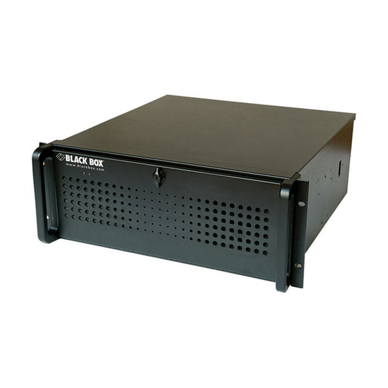
Chapter 2: Overview 2. Overview 2.1 Introduction The VWP-2040 wall controller is a high quality, flexible solution for smaller, more compact video wall and multi- screen display applications. The controller is optimized for operation Radian Video Wall Processor PCI express graphics and video capture cards. -
Page 24: Available Components
Chapter 2: Overview 2.3 Available Components Table 2-1. Radian Video Wall Processor components. Radian Video Wall Processor Components Chassis Product Code Number of Slots Signal Format VWP-2040 4-slot chassis Depends on cards installed VWP-2090 9-slot chassis Depends on cards installed VWP-2110 11-slot chassis Depends on cards... -
Page 25: What's Included
Chapter 2: Overview 2.4 What's Included Your package should contain the following items. If anything is missing or damaged, contact Black Box Technical Support at 877-877-2269 or info@blackbox.com. 2.4.1 VWP-2040 • VWP-2040 Chassis • USB keyboard • USB mouse • (2) power cables •... -
Page 26: Hardware Description
Chapter 2: Overview 2.5 Hardware Description 2.5.1 VWP-2040 • Industrial PC with 4 PCIe slots • Core i5 Haswell CPU 3.4GHz PICMG1.3 ® • ASUS Z87-WS Haswell Generation motherboard • 4 x PCIe 3.0/2.0 (Dual x16 0r x16/x8/x8 or quad x8* •... - Page 27 Chapter 2: Overview Figure 2-2. Back panel of the VWP-2040. Table 2-3. Back panel components. Number in FIgure 2-2 Component Power Switches Outputs: Mini-DisplayPort/HDMI/ DisplayPort Ethernet Ports USB Ports Figure 2-3. VWP-2040 motherboard layout. 877-877-2269 | blackbox.com Page 27...
- Page 28 Chapter 2: Overview Table 2-4. Motherboard components. Number in FIgure 2-3 Component 4 x DIMM, 2800(O.C) 1600 Up to 32GB 4 x SATA3 6Gb/s ports 6 x SATA3 6GB/s ports PCIe Slot 1, x16 (Gen3 x16/8 link) PCIe Slot 2 x16 (Gen3 x8/0 link) PCIe Slot 3 x16 (Gen3 x16/8 link) PCIe Slot 4 x16 (Gen3 x8/0 link)s Figure 2-4.
-
Page 29: Vwp-2090
Chapter 2: Overview 2.5.2 VWP-2090 The VWP-2090 system incorporates the PCI Express9-G3 switched fabric backplane, providing 9 high band- width PCIe slots for use with any Radian Video Wall Processor video capture or graphics card. It also has SBC4, a single board computer featuring an Intel Core i7 processor with up to 16 GB of DDR3 memory and on-board ®... - Page 30 Chapter 2: Overview Figure 2-6. Back panel of the VWP-2090. Table 2-7. Back-panel components. Number in FIgure 2-6 Component Power Switches USB Ports Ethernet Ports DVI-I Output 877-877-2269 | blackbox.com Page 30...
-
Page 31: Vwp-2110
Chapter 2: Overview 2.5.3 VWP-2110 The VWP-2110 is an industrial PC incorporating an 11-slot PCIe backplane. The switched fabric technology provides 11 x 8 lane PCIe slots that have x 16 physical connectors, and each slot can provide up to 8 Gbps bidirectional bandwidth. -
Page 32: Video Graphics And Capture Cards
Chapter 2: Overview Figure 2-8. Back panel of the VWP-2110. Table 2-9. Back-panel components. Number in FIgure 2-8 Component Power Switches USB Ports Ethernet Ports DVI-I Output 2.5.4 Video Graphics and Video Capture Cards Your Radian Video Wall Processor is shipped from the factory with all Video Graphics and Video Capture Cards and software installed. -
Page 33: Cables And Adapters
Chapter 2: Overview 2.5.5 Cables and Adapters Figure 2-9. Cables and adapters. Table 2-10. Cables and adapters Number in FIgure 2-9 Component DVI-VGA adapter DVI-Component Adapter DVI-HDMI Adapter DVI splitter cable Composite S-Video input cable Power cables 877-877-2269 | blackbox.com Page 33... -
Page 34: Onboard Graphics Adapter
Chapter 3: Onboard Graphics Adapter 3. Onboard Graphics Adapter Each VWP-2040, VWP-2090, or VWP-2110 shipped by Black Box is custom built. If cards are not pre-installed, then you will need to install the software. For information on software installation, consult the softwaremanual on blackbox.com. -
Page 35: Using The Onboard Graphics Adapter For The Vwp-2040
Chapter 3: Onboard Graphics Adapter 3.2 Using the Onboard Graphics Adapter for the VWP-2040 3.2.1 Onboard Graphics Adapter used as Control Screen (VWP-2040) The VWP is shipped with the BIOS configured to boot from the onboard graphics device. This output can then be used as the control screen for a typical wall configuration. -
Page 36: Using The Onboard Graphics Adapter For The Vwp-2090 Or Vwp-2110
Chapter 3: Onboard Graphics Adapter 3.3 Using the Onboard Graphics Adapter for the VWP-2090 or VWP-2110 3.3.1 Onboard Graphics Adaptor used as Control Screen (VWP-2090 or VWP-2110) The VWP-2090 or VWO-2110 is shipped with the BIOS configured to boot from the onboard graphics device. This output can then be used as the control screen for a typical wall configuration. -
Page 37: Onboard Graphics Adapter Disabled (Vwp-2090 Or Vwp-2110)
Chapter 3: Onboard Graphics Adapter 3.3.2 Onboard Graphics Adaptor Disabled (VWP-2090 or VWP-2110) If you do not require a control screen, then you should disable the integrated graphics as described below. Connect a monitor to the onboard graphics device output and enter setup from the boot screen by pressing <F2>... -
Page 38: Hardware Installation
Chapter 4: Hardware Installation 4. Hardware Installation 4.1 VWP-2040 Your VWP-2040 arrives with all necessary cards installed. If you want to add more cards, refer to the Appendixes in this manual for installation instructions. 4.2 VWP-2090 Backplane Layout Your VWP-2090 may have cards that require installation because cards may have been shipped separately. To ensure your cards are installed correctly, consult the appendixes in this manual for detailed instructions. - Page 39 Chapter 4: Hardware Installation Table 4-2. VWP-2090 backplane components. Component Description Component Description FAN1, FAN2, 4 pin fan speed control header J11, J12 SATA 2.0 FAN3 Pin 1 : GND Pin 1 : 0V Pin 5 : B- Pin 2 : +12V Pin 2 : A+ Pin 6 : B+ Pin 3 : TACH...
-
Page 40: Connecting The Vwx-2090 Expansion Chassis To Vwp-2090 Radian Video Wall Processor Chassis
Chapter 4: Hardware Installation 4.3 Connecting the VWX-2090 Expansion Chassis to the VWP-2090 Radian Video Wall Processor Chassis You can connect a VWX-2090 expansion chassis to the VWP-2090 to increase the number of PCIe slots available. Figure 4-2. Connect the expansion chassis. Connect the chassis to the expansion chassis via the appropriate cable. - Page 41 Chapter 4: Hardware Installation VWP-2090 and VWX-2090 LED indicators. The VWP-2090 and VWX-2090 have an LED for each PCIe slot and the PICMG1.3 SBC slot. Figure 4-4. LEDs on the VWP-2090 and VWX-2090. Table 4-3. LEDs on the VWP-2090 and VWX-2090. Description LED1 ON = +5V Standby Voltage present...
-
Page 42: Vwp-2110 Backplane Layout
Chapter 4: Hardware Installation 4.4 VWP-2110 Backplane Layout Your VWP-2110 may have cards that require installation because cards may have been shipped separately. To ensure your cards are installed correctly, consult the appendixes in this manual for detailed instructions. VWP-2110 Backplane Layout The VWP-2110 is fitted with the G3 backplane. - Page 43 Chapter 4: Hardware Installation Table 4-4. VWP-2110 PCIe port width. Slot Port Width PICMG Slot 1 Slot 2 Slot 3 Slot 4 Slot 5 Slot 6 Slot 7 Slot 8 Slot 9 Slot 10 Slot 11 877-877-2269 | blackbox.com Page 43...
- Page 44 Chapter 4: Hardware Installation Table 4-5. VWP-2110 backplane components. Component Description Component Description FAN1, FAN2, 4 pin fan speed control header J30, J31 SATA 2.0 FAN3 Pin 1 : GND Pin 1 : 0V Pin 5 : B- Pin 2 : +12V Pin 2 : A+ Pin 6 : B+ Pin 3 : TACH...
-
Page 45: Connecting The Vwx-2100 Expansion Chassis To Vwp-2110 Radian Video Wall Processor Chassis
Chapter 4: Hardware Installation 4.5 Connecting the VWX-2110 Expansion Chassis to the VWP-2110 Radian Video Wall Processor Chassis You can connect a VWX-2110 expansion chassis to the VWP-2110 to increase the number of PCIe slots available. The following diagram illustrates how this can be achieved. Figure 4-6. - Page 46 Chapter 4: Hardware Installation If your Radian Video Wall Processor Chassis does not arrive from the factory fully populated with cards, refer to the Appendixes for diagrams and installation instructions for each available card option that can work with the Chassis.
-
Page 47: Software Overview
Chapter 5: Software Overview 5. Software Overview Each Radian Video Wall Processor is custom built. If cards are not pre-installed, then you will need to install soft- ware/drivers. For information on software installation, consult the relevant user manual on blackbox.com. If you ordered VWS-2001 Video Wall Controller Software, it will be installed prior to shipment. -
Page 48: Video Capture Card Software
Chapter 5: Software Overview Audio Support Both digital and analog audio are supported for Video Wall Controller windows, depending on the Video Capture Card installed in the system. Audio support allows the configuration of embedded digital and analog audio capture inputs. Carousel When configured, the Carousel function automatically cycles through lists of different Video and IP camera inputs at set time intervals. - Page 49 Chapter 5: Software Overview • Low Input to Output Capture Latency. • DMA to third party graphics vendors back and front buffers via Direct3D. • Compatibility with AMD DirectGMA. • Compatibility with Nvidia GPUDirect. • User Mode filter for source selection. •...
-
Page 50: Filter Maintenance (Vwp-2090 Or Vwp-2110)
You can use a vacuum cleaner to clean the filter. NOTE: Do not immerse the filter in water or any other cleaning liquid. For advice on replacement filters, contact Black Box Technical Support at 877-877-2269 or info@blackbox.com. 877-877-2269 | blackbox.com... -
Page 51: Appendix A. Installing The Video Graphics Card (Vgc-Hdmi-2-4 Or Vgc-Hdmi-2K-4)
Appendix A: Installing the Video Graphics Card Appendix A. Installing the Video Graphics Card (VGC-HDMI-2-4 or VGC-HDMI-2K-4) Table A-1. Video Graphics Cards Video Graphics Cards Product Code Outputs Signal Format VGC-HDMI-2-4 HDMI graphics card, up to 4K resolution HDMI VGC-HDMI-2K-4 HDMI graphics card, up to 2K resolution HDMI A.1 Introduction... -
Page 52: Installing The Video Graphics Card
This should hasten any query if you need to contact Black Box Technical Support. The serial number is displayed on the card and the box label. -
Page 53: Installing The Display Drivers
The system limitations are the amount of address space available and the capacity of the power supply. Consult Black Box Technical Support at 877-877-2269 or info@blackbox.com if you have any problems installing multiple cards. The amount of current a power supply can deliver on each voltage rail is limited. There may also be a limit on the total power. - Page 54 Appendix A: Installing the Video Graphics Card There are a number of different BIOS types in operation as the computer boots. The “System BIOS” is resident on the motherboard and is responsible for starting up all the hardware and mapping in the resources (like the I/O) so that they are available to the CPU.
-
Page 55: Card Ordering
Appendix A: Installing the Video Graphics Card A.5 Card Ordering To connect up to 64 screens to Video Graphics Cards, configure the links as shown in the diagram below. Figure A-2. Card numbering on the link header. The links control the order in which the display driver uses the Video Graphics Cards. Knowing the order that the Video Graphics Cards use will help when connecting the screens and the outputs from video switches. - Page 56 Appendix A: Installing the Video Graphics Card DisplayPort Outputs The Video Graphics Card has four DisplayPort connectors that allow full-size, locking cables capable of driving next generations displays. When used in conjunction with the extender modules (powered via the Video Graphics Card), cable lengths of up to 96 feet (30 meters) can be achieved.
-
Page 57: Multi-Screen Configuration
Appendix A: Installing the Video Graphics Card A.6 Multi-Screen Configuration To change the display settings for the Video Graphics Cards, use the Display Properties dialog in the Control Panel. Display: 2. (Default Monitor) on Video Graphics Card (example only; this is a dropdown menu box) Resolution: 5120 x 4096 (example only;... - Page 58 Appendix A: Installing the Video Graphics Card Figure A-4. Monitor Configuration screen. Resolution per Screen: Figure A-5. Resolution per screen slider bar. NOTE: Changing the resolution may alter the color palette settings, so check that it is correct before clicking OK or Apply.
- Page 59 Appendix A: Installing the Video Graphics Card Source of Mode: Figure A-6. Source of Mode screen. When the TWIN tab is selected, the display driver reads the EDID information from each monitor and reads the Registry to find detailed display timing information. The Source of Mode group box shows which mode sources are available for the selected resolution and color depth.
-
Page 60: Defining Custom Modes
To define custom modes, use the Custom Mode Utilities tool on the Radian Video Wall Processor thumb drive. You can also download the latest version from the Black Box website: www.blackbox.com The Custom Modes tool is a utility for defining custom modes that can be generated by the Video Graphics Card. -
Page 61: Appendix B. Installing The Video Capture Cards
Appendix B: Installing the Video Capture Cards Appendix B. Installing the Video Capture Cards The available Video Capture Cards and their connectors are listed in Table B-1. Sections B.1 through B.9 provide installation instructions for each Video Capture Card. Table B-1. Video Capture Cards Product Code Connectors Supported Inputs... -
Page 62: Video Capture Card (Vcc-Sd-Hd-A-2)
Appendix B: Installing the Video Graphics Cards B.1 Video Capture Card (VCC-SD-HD-A-2): (1) HD channel + (1) SD channel + AM2 + cable, full height Figure B- 1. Video Capture Card (VCC-SD-HD-A-2) illsutrated. B.1.1 Introduction The Video Capture Card (VCC-SD-HD-A-2) has two independent video capture channels—one supporting HD capture and a second simultaneously decoding Standard Definition composite video. -
Page 63: What's Included
This should hasten any query if you need to contact Black Box Technical Support. The serial number is displayed on the card itself and the box label. -
Page 64: How To Connect Input Sources
Appendix B: Installing the Video Capture Cards B.1.5 How to Connect Input Sources The VCC-SD-HD-A-2 card has one DVI-I and one RCA (female) connector, and one RGB (male) connector on the Audio Module: The DVI-I connector supports DVI, HDMI, Component and RGB (VGA) inputs using the supplied adapters where required. - Page 65 Appendix B: Installing the Video Capture Cards An RGB (VGA) input is connected to the DVI-I connector using the supplied DVI-VGA Adapter: Figure B-5. RGB (VGA) input. A standard definition signal can be connected to the RCA connector on the VCC-SD-HD-A-2. Figure B-6.
-
Page 66: Installing Multiple Cards
Appendix B: Installing the Video Capture Cards Table 8-2. Audio feed input signals. Connector Signal Balanced (XLR) input left Balanced (XLR) Input Right Unbalanced Input Left Unbalanced Input Right Audio Out Left Audio Out Right B.1.6 Installing Multiple Cards You can install multiple cards in a system, providing a large number of capture channels. Combinations of Video Capture Cards in the same machine are supported by the driver. -
Page 67: Firmware Upgrades
The program will run, but no notifications are displayed. B.1.7 Firmware Upgrades The VCC-SD-HD-A-2 cards allow you to upgrade firmware on site rather than returning the card to Black Box. Whenever a firmware upgrade is performed, the J11 Link MUST BE FITTED on the Video Capture Card. To perform the upgrade, follow the step-by-step instructions provided by the upgrade application. -
Page 68: Hardware Overview
This should hasten any query if you need to contact Black Box Technical Support. The serial number is displayed on the card itself and the box label. -
Page 69: How To Connect Input Sources
Appendix B: Installing the Video Capture Cards 3. Locate a vacant PCI Express slot (x4 or higher) on the motherboard and remove the blanking plate (retain all screws). NOTE: If you are in doubt, consult your motherboard documentation to correctly identify a PCI Express slot. If the card is forced into a 32 or 64 bit PCI or PCI-X slot, it will be irreparably damaged when the system is powered up and the warranty will be void. - Page 70 Appendix B: Installing the Video Capture Cards An RGB (VGA) input is connected to the DVI-I connector using the supplied DVI-VGA Adapter: Figure B-13. RGB (VGA) input. A standard definition signal can be connected to the RCA connector on the VCC-SD-HD-A-2. Figure B-14.
-
Page 71: Installing Multiple Cards
Appendix B: Installing the Video Capture Cards Table 8-3. Audio feed input signals. Connector Signal Balanced (XLR) input left Balanced (XLR) Input Right Unbalanced Input Left Unbalanced Input Right Audio Out Left Audio Out Right B.2.6 Installing Multiple Cards You can install multiple cards in a system, providing a large number of capture channels. Combinations of Radian Video Wall Controller capture cards in the same machine are supported by the Vision driver. -
Page 72: Firmware Upgrades
The program will run, but no notifications are displayed. B.2.7 Firmware Upgrades The VCC-SD-HD-3 cards allow you to upgrade firmware on site rather than returning the card to Black Box. Whenever a firmware upgrade is performed, the J8 Link MUST BE FITTED on the VCC-SD-HD-3. -
Page 73: Video Capture Card (Vcc-Sdi-Sd-Hd-3)
Appendix B: Installing the Video Capture Cards B.3 Video Capture Card (VCC-SDI-SD-HD-3): (1) HD channels + (1) HD-SDI channel + (1) SD channel, full height Figure B-17. Video Capture Card (VCC-SD-SDI-HD-3) illustrated. B.3.1 Introduction The VCC-SDI-SD-HD-3 has three independent video capture channels—one supporting HD capture, a second decoding Standard Definition composite video and the third, an HD-SDI capture supporting SD-SDI, HD-SDI, and 3G-SDI—all channels can be captured simultaneously. -
Page 74: What's Included
This should hasten any query if you need to contact Black Box Technical Support. The serial number is displayed on the card itself and the box label. -
Page 75: How To Connect Input Sources
Appendix B: Installing the Video Capture Cards B.3.5 How to Connect Input Sources The VCC-SDI-SD-HD-3 card has one DVI-I, one RCA (female) connector, and one BNC (Green LED) connector. The DVI-I connector supports DVI, HDMI, Component and RGB (VGA) inputs using adapters where required. A DVI input is connected directly into the DVI-I connector, which accepts DVI-D (digital) or DVI-A (analog) inputs. - Page 76 Appendix B: Installing the Video Capture Cards An RGB (VGA) input is connected to the DVI-I connector using the supplied DVI-VGA Adapter: Figure B-21. RGB (VGA) input. A standard definition signal can be connected to the RCA connector on the VCC-SDI-SD-HD-3 . Figure B-22.
- Page 77 Appendix B: Installing the Video Capture Cards Cable Length The VCC-SDI-SD-HD-3 supports cable lengths of up to 480 feet (150 meters). for 3G-SDI. This figure is based on using low-loss coax cable (Belden 1694A). Using the Optional Audio Module (AM2) Audio is connected to the AM2 using the Audio Break Out cable provided with the AM2.
-
Page 78: Installing Multiple Cards
The VCC-SDI-SD-HD-3 cards allow firmware upgrade to be completed on site rather than returning the card to Black Box. Whenever a firmware upgrade is performed, the J8 Link MUST BE FITTED on the VCC-SDI-SD-HD-3. To perform the upgrade, follow the step-by-step instructions provided by the upgrade application. -
Page 79: Software Installation
Appendix B: Installing the Video Capture Cards If something goes wrong during the upgrade process (e.g., system power outage), you can revert to the factory settings by powering down the system, temporarily removing the J8 link, then powering up the system with the link removed. -
Page 80: Video Capture Card (Vcc-Hd-4)
Appendix B: Installing the Video Capture Cards B.4 Video Capture Card (VCC-HD-4): (4) channel DVI/RGB/HD capture card Figure B-26. Video Capture Card (VCC-HD-4) illustrated. B.4.1 Introduction The VCC-HD-4 has four on-board video capture channels: two HDMI 1.4 channels offer 3840 x 2160 @ 30 frames per second (fps) and two HDMI 1.3 channels offer 1920 x 1080 @ 60 fps, all operating independently of each other. -
Page 81: What's Included
This should hasten any query if you need to contact Black Box Technical Support. The serial number is displayed on the card itself and the box label. -
Page 82: How To Connect Input Sources
Appendix B: Installing the Video Capture Cards B.4.5 How to Connect Input Sources A DVI input connects directly into the DVI-I connector that accepts DVI-D (digital) or DVI-A (analog) inputs. Figure B-28. DVI input. An HDMI input is connected to the DVI-I connector using the supplied DVI-HDMI Adapter. Figure B-29. -
Page 83: Installing Multiple Cards
Appendix B: Installing the Video Capture Cards An RGB (VGA) input is connected to the DVI-I connector using the supplied DVI-VGA Adapter: B-31. RGB (VGA) input. B.4.6 Installing Multiple Cards Multiple cards can be installed in a system, providing a large number of capture channels. Combinations of Radian Video Wall Processor capture cards in the same machine are supported by the Radian Video Wall Processor driver. -
Page 84: Firmware Upgrades
B.4.7 Firmware Upgrades The VCC-HD-4 cards allow you to upgrade firmware on site rather than returning the card to Black Box. Whenever a firmware upgrade is performed, the SW2 on the DIP switch must be set ON. The DIP Switch can be located on the back of the VCC-HD-4 To perform the upgrade, follow the step-by-step instructions provided by the upgrade application. -
Page 85: Hardware Overview
This should hasten any query should you need to contact Black Box Technical Support. The serial number is displayed on the card itself and the box label. -
Page 86: How To Connect Input Sources
Appendix B: Installing the Video Capture Cards NOTE: If you are in doubt, consult your motherboard documentation to correctly identify a PCI Express slot. If the card is forced into a 32 or 64 bit PCI or PCI-X slot, it will be irreparably damaged when the system is powered up and the warranty will be void. -
Page 87: Installing Multiple Cards
Appendix B: Installing the Video Capture Cards Cable Settings When using the VCC-DP-2, a cable settings function becomes available in the Input Settings of the software appli- cation. DisplayPort sources often train the cable link at the maximum available bit rate, even if it is not needed for the required display resolution. -
Page 88: Firmware Upgrades
8.5.7 Firmware Upgrades The VCC-DP-2 cards allow firmware upgrade to be completed on site rather than returning the card to Black Box. Whenever a firmware upgrade is performed, the SW2 on the DIP switch must be set ON. The DIP Switch can be located on the back of the VCC-DP-2. -
Page 89: Video Capture Card (Vcc-Hd-4-H Or Vcc-Hd-4-D)
Appendix B: Installing the Video Capture Cards B.6 Video Capture Card (VCC-HD-4-H or VCC-HD-4-D) Figure B- 38. VCC-HD-4-H or VCC-SD-HD-4-D B.6.1 Introduction The VCC-HD-4 has four on board video capture channels; two channels of HDMI 1.4 offering 3840 x 2160 @ 30 frames per second (fps) and two HDMI 1.3 channels offering 1920 x 1080 @ 60 fps, all operating independently of each other. -
Page 90: What's Included
Appendix B: Installing the Video Capture Cards • Direct Show interface. • RGBEasy API. Models VCC-HD-4-H - Capture card with 2 x HDMI splitter cables. VCC-HD-4-D - Capture card with 2 x DVI splitter cables. B.6.3 What's Included Your packing box should contain the following items: VCC-HD-4 - Quad HDMI video capture card and depending on which model ordered, either: •... -
Page 91: How To Connect Input Sources
Appendix B: Installing the Video Capture Cards B.6.5 How to Connect Input Sources The VCC-HD-4 card has two DSM59 connectors. The connectors support DVI or HDMI using the supplied splitter cables where required. Figure B-39. Connecting input sources. Be careful when connecting the splitter cables to the VCC-HD-4 card. Do not force the cable into the connector. Forcing the cable into the connector could cause damage not covered by the warranty. -
Page 92: Installing Multiple Cards
Appendix B: Installing the Video Capture Cards B.6.6 Installing Multiple Cards Multiple cards can be installed in a system providing a large number capture channels. Combinations of Radian Video Wall Processor capture cards in the same machine are supported by the Radian Video Wall Processor driver. -
Page 93: Firmware Upgrades
The VCC-HD-4-H and VCC-HD-4-D cards allow firmware upgrade to be completed on site rather than returning the card to Black Box. Whenever a firmware upgrade is performed, the SW2 on the DIP switch must be set ON. The DIP Switch can be located on the back of the VCC-HD-4-H or VCC-HD-4-D. To perform the upgrade, follow the step-by-step instructions provided by the upgrade application. -
Page 94: Hardware Overview
This should hasten any query if you need to contact Black Box Technical Support. The serial number is displayed on the card itself and the box label. -
Page 95: How To Connect Input Sources
Appendix B: Installing the Video Capture Cards B.7.5 How to Connect Input Sources The VCC-SDI-4 card has four BNC type connectors for four separate, simultaneous inputs. The connectors have green LEDs. Connect the cables to distribute the video source signal to BNC input connectors on the VCC-SDI-4 capture card. -
Page 96: Installing Multiple Cards
Appendix B: Installing the Video Capture Cards B.7.6 Installing Multiple Cards Figure B-43. Card ordering. Multiple cards can be installed in a system, providing a large number capture channels. Combinations of Radian Video Wall Processor capture cards in the same machine are supported by the Radian Video Wall Processor driver. -
Page 97: Firmware Upgrades
This should hasten any query if you need to contact Black Box Technical Support. The serial number is displayed on the card itself and the box label. -
Page 98: Installing Vcc-Stream Cards
Appendix B: Installing the Video Capture Cards Each VCC-STREAM card can capture a bandwidth equivalent to twelve 1920 x 1080 @ 30Hz streams on to any wall controller that uses Radian Video Wall Processor graphics cards. The number of streams the VCC-STREAM provides depends on a number of factors, such as the decoder profile used. - Page 99 Appendix B: Installing the Video Capture Cards The VCC-STREAM card has two Ethernet ports and one currently dormant output DisplayPort connector (reserved for future use). Figure B-45. Connecting input sources. Connect a network cable into one or both of the Ethernet ports. Be careful when connecting a network cable. Make sure the cable connector is pushed firmly into the Ethernet port until you hear a definite click.
-
Page 100: Ip Addressing
Appendix B: Installing the Video Capture Cards The green LEDs are labelled 0-5 and 8-11 these map to LEDs D4 to D13. Table B-6. LEDs. LED Link Lane LED Status Normal Operation PCI Host Link lane 0 On=Gen 2 Flashing=Gen 1 Off=Link not On - Gen 2 trained... -
Page 101: Software Overview
Appendix B: Installing the Video Capture Cards Black Box VCC-STREAM Figure B-48. IP address screen. LAN1 and LAN2 operate independently. They both require configuring as a Static IP address. Repeat this process for LAN2 by clicking on the LAN2 tab. -
Page 102: Troubleshooting
The VCC-STREAM cards allow firmware upgrades to be completed on-site rather than returning the card to Black Box. Whenever a firmware upgrade is performed, the JP8 Link MUST BE FITTED on the VCC-STREAM card. To perform the upgrade, follow the step-by-step instructions provided by the upgrade application. -
Page 103: Appendix C: Installing The Expansion Chassis
Appendix C: Installing the Expansion Chassis Appendix C. Installing the Expansion Chassis Available models include: • Expansion Chassis (VWX-2090), 600 W RPSU, works with VWP-2090. • Expansion Chassis (VWX-2110), 800 W RPSU, works with VWP-2110. See Chapter 3 for more information. 877-877-2269 | blackbox.com Page 103... -
Page 104: Appendix D: Radian Video Wall Processor Software Capabilities
Appendix D: Radian Video Wall Processor Software Capabilities Appendix D. Radian Video Wall Processor Software Capabilities • Timestamp support for streaming synchronization. • Synchronize multiple inputs across multiple cards. • Synchronize systems using network clock synchronization. • Use for edge blending and other applications. •... - Page 105 Appendix D: Radian Video Wall Processor Software Capabilities NOTE: The supplied drivers and software require that you use: • Windows XP, Windows Vista, Windows Server 2003, Windows Server 2008, Windows 7 (x86 and x64 Operating Systems), Windows 8, or Linux (audio not supported) •...
- Page 106 © Copyright 2016, 2022. Black Box Corporation. All rights reserved. Black Box and the Double Diamond logo are registered trademarks of ®...
Need help?
Do you have a question about the Radian VWP-2040 and is the answer not in the manual?
Questions and answers