Advertisement
Quick Links
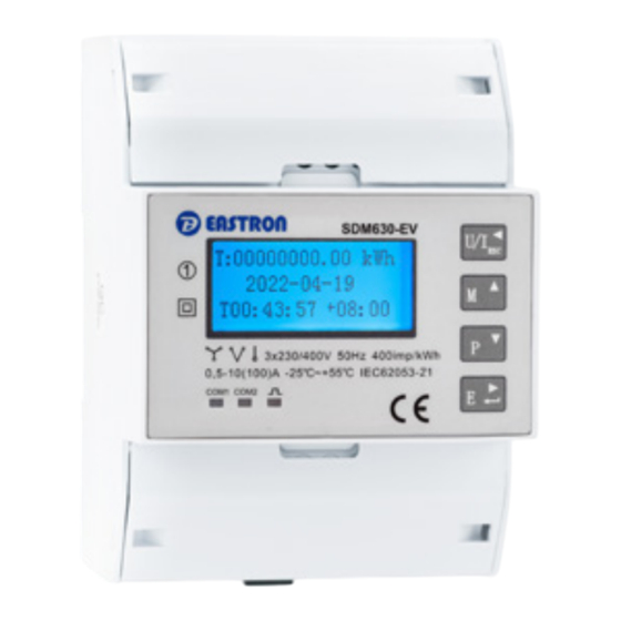
SDM630-EV
DIN Rail Smart Meter for Single and
Three Phase Electrical Systems
User Manual
2022 V1.0
•
Measures kWh Kvarh, KW, Kvar, KVA, P, F,
PF, Hz, dmd, V, A, etc.
•
Bi-directional measurement IMP & EXP
•
Pulse output
•
RS485 Modbus
•
Din rail mounting 35mm
•
100A direct connection
•
Better than Class 1 / B accuracy
1. Introduction
The SDM630-EV V2 measures and displays the
characteristics of single phase two wires (1p2w),
three phase three wires (3p3w,) and three phase four
wires(3p4w) supplies, including voltage, frequency,
current, power ,active and reactive energy, imported or
exported. Energy is measured in terms of kWh, kVArh.
Maximum demand current can be measured over preset
periods of up to 60 minutes. In order to measure energy,
the unit requires voltage and current inputs in addition to
the supply required to power the product.
SDM630-EV V2 supports max. 100A direct connection,
saves the cost and avoid the trouble to connect external
CTs, giving the unit a cost-effective and easy operation.
Built-in interfaces provides pulse and RS485 Modbus RTU
outputs. Configuration is password protected.
1.2 Measured Parameters
The unit can monitor and display the following parameters
of a single phase two wire(1p2w), three
phase three wire(3p3w) or four phase four wire(3p4w)
supply.
1.3 Voltage and Current
Phase to neutral voltages 100 to 289V a.c.
(not for 3p3w supplies)
Voltages between phases 173 to 500V a.c.
(3p supplies only)
Percentage total voltage harmonic distortion (THD%) for
each phase to N ( not for 3p3w supplies)
Percentage voltage THD% between phases (three phase
supplies only)
Current THD% for each phase
1.4 Power Factor and
Frequency and Max. Demand
Frequency in Hz
Instantaneous power:
Power 0 to 99999 W
Reactive Power 0 to 99999 VAr
Volt-amps 0 to 99999 VA
Maximum demanded power since last Demand reset
Power factor
Maximum neutral demand current, since the last Demand
reset (for 3p4w supply only)
1.5 Energy Measurements
•
Imported active energy
0 to 999999.99 kWh
•
Exported active energy
0 to 999999.99 kWh
•
Imported reactive energy
0 to 999999.99 kVArh
•
Exported reactive energy
0 to 999999.99 kVArh
•
Total active energy
0 to 999999.99 kWh
•
Total reactive energy
0 to 999999.99 kVArh
1.6 Measured Inputs
Voltage inputs through 4-way fixed connector with 25mm²
stranded wire capacity. single phase two wire(1p2w), three
phase three wire(3p3w) or four phase four wire(3p4w)
unbalanced. Line frequency measured from L1 voltage or
L3 voltage.
1.7 Accuracy
•
Voltage
0·5% of range maximum
•
Current
0·5% of nominal
•
Frequency
0·2% of mid-frequency
•
Power factor
1% of unity (0.01)
•
Active power (W)
±1% of range maximum
•
Reactive power (VAr)
±1% of range maximum
•
Apparent power (VA)
±1% of range maximum
•
Active energy (Wh)
Class 1 IEC 62053-21
Class B EN50470-1/3
•
Reactive energy (VArh)
Class 2 IEC 62053-23
•
Response time to step input 1s, typical, to >99% of
final reading, at 50 Hz.
If you have any question, please feel free to contact our sales team. Tel: 0203 758 3494 Email: sales@eastroneurope.com www.eastrongroup.com
1.8 Interfaces for External
Monitoring
Three interfaces are provided:
•
2 RS485 communication channels via protocol remotely.
•
Pulse output indicating real-time measured energy.
1.9 Pulse Output
Pulse output is non-configurable. It is fixed up with active
kWh. The constant is 400imp/kWh.
1.10 RS485 Output for
Modbus RTU
There 2 two channels of RS485 Modbus RTU.
For Modbus RTU, the following RS485 communication
parameters can be configured from the
Set-up menu:
•
1st Modbus Output (configurable):
Baud rate 2400, 4800, 9600(default), 19200, 38400
Parity none (default)/odd/even
Stop bits 1 or 2
RS485 network address nnn – 3-digit number,
001 to 247
•
2nd Modbus Pitput (non-configurable):
Baud rate 9600
Parity none
Stop bits 1
Modbus™ Word order Hi/Lo byte order is set
automatically to normal or reverse. It cannot be
configured from the set-up menu.
1.11 Reference Conditions of
Influence Quantities
Influence Quantities are variables that affect measurement
errors to a minor degree. Accuracy is
verified under nominal value (within the specified tolerance)
of these conditions.
•
Ambient temperature
23°C ±1°C
•
Input frequency
50Hz(MID)
50 or 60Hz ±2%
(non- MID)
•
Input waveform
Sinusoidal (distortion
factor < 0·005)
•
Magnetic field of external origin
Terrestrial flux
1.12 Environment
•
Operating temperature
3K6(-25°C to
+55°C*),Default
3K7(-40°C to +70°C*)
•
Storage temperature
-40°C to +70°C*
•
Relative humidity
0 to 90%, non-
condensing
•
Altitude
Up to 2000m
•
Warm up time
5S
•
Vibration
10Hz to 50Hz,
IEC 60068-2-6, 2g
•
Shock
30g in 3 planes
* Maximum operating and storage temperatures are in the context of
typical daily and seasonal variation.
1.13 Unit Characteristics
The Unit can measure and display:
•
Line voltage and THD% (total harmonic distortion)
of all phases
•
Line Frequency
•
Currents, Current demands and current THD% of
all phases
•
Power, maximum power demand and power factor
•
Active energy imported and exported
•
Reactive energy imported and exported
The unit has password-protected set-up screens for:
•
Changing password
•
Supply system selection 1p2w, 3p3w,3p4w
•
Demand Interval Time(DIT)
•
Reset for demand measurements
The pulse output indicates real-time energy measurement.
2 RS485 outputs allows remote monitoring from another
display or a computer.
2. Start-up Screens
The interface performs a
self-test and indicates the
result if the test passes.
The second screen
indicates the firmware
installed in the unit and its
build number.
*The build number(41
01.00) is for reference only.
The actual build number
changes according to
product requirements.
Meter SN, Modbus ID and
baud rate setting
After a short delay, the screen will display active energy
measurements.
2.1 Measurements
The buttons operate as follows:
Selects the Voltage and Current display screens
In Set-up Mode, this is the "Left" or "Back" button.
Select the Frequency and Power factor display
screens
In Set-up Mode, this is the "Up" button
Select the Power display screens
In Set-up Mode, this is the "Down" button
Select the Energy display screens
In Set-up mode, this is the "Enter" or "Right" button
2.2 Voltage and Current
Each successive pressing of the
button selects
a new range:
Phase to neutral
voltages(3p4w)
Phase to neutral
voltages(3p3w)
Current on each phase
Neutral current
2.3 Frequency and Power
Factor and Demand
Each successive pressing of the
button selects
a new range:
Power Factor
Maximum Current Demand
Maximum Power Demand
2.4 Power
Each successive pressing of the
button selects
a new range:
Instantaneous Active
Power in W
Instantaneous Reactive
Power in VAr
Instantaneous Volt-amps
in VA
Total W, VArh, VA
2.5 Energy Measurements
Each successive pressing of the
button selects
a new range:
Total kWh and time will be
showed when no charging
Total kWh and charged
kWh will be showed when
charging
CSID Numbers And current
time will be showed when
charging
Total active kWh, import
active kWh, export active
kWh
Total reactive kWh, import
reactive kWh, export
reactive kWh
2.6 Set-up
To enter set-up mode, pressing the
button for 3
seconds, until the password screen appears.
PASSWORD :
0
0 0 0
Setting up is password-protected so you must enter the
correct password (default '1000') before processing. If
an incorrect password is entered, the display will show:
PASS Err
To exit setting-up mode, press
repeatedly until
the measurement screen is restored.
Setting - Button operation
3 Set-up Entry Methods
Some menu items, such as password, require a four-digit
number entry while others, such as supply system, require
selection from a number of menu options.
3.1 Menu Option Selection
1) Use the
and
buttons to select the
required item from the menu. Selection does not roll over
between bottom and top of list.
2) Press
to confirm your selection.
3) If an item flashes, then it can be adjusted by the
and
buttons. If not, there maybe a further layer.
4) Having selected an option from the current layer press
to confirm your selection. The SET indicator will appear.
5) Having completed a parameter setting, press
return to a higher menu level. The SET indicator will be
removed and you will be able to use the
and
buttons for further menu selection.
6) On completion of all set-up, press
repeatedly
until the measurement screen is restored.
3.2 Number Entry Procedure
When setting up the unit, some screens require the
entering of a number. In particular, on entry to the setting
up section, a password must be entered. Digits are set
individually, from left to right.
The procedure is as follows:
1) The current digit to be set flashes and is set using
the
and
buttons.
2) Press
to confirm each digit setting. The SET
indicator appears after the last digit has been set.
3) After setting the last digit, press
to exit the
number setting routine.
3.3 Main set
1.Main
1.1Sytem Type
3P4W
1.2Password
1000
1.3Reset
DMD
System type
From the Set-up menu, use
and
buttons to select the System option. The screen
will show the currently selected system type.
Password
Use the
and
to choose the change
password option.
Reset
Press to enter the selection routine. If succeed,
the cursor will jump back to Reset.
Press
to exit the number setting routine and return to the
Set-up menu. SET will be removed.
3.4 Communication set
2.Communication
2.1Addr
002
2.2Baud
9600
2.3Parity
NONE
Addr
From the Set-up menu, use
and
buttons to select the Address ID.
Baud
From the Set-up menu, use
and
buttons to select the Baud Rate option.
Parity
From the Set-up menu, use
and
buttons to select the Parity option.
3.5 Time set
4.Time
4.Time
4.1Data
14-01-30
4.4ZONE
4.2Time
08-15-14
4.5Backlight
4.3DMD
60
Data
From the Set-up menu, use
and
buttons to select the data.
Use
to move cursor
Time
From the Set-up menu, use
and
buttons to select the data.
Use
to move cursor
DMD
From the Set-up menu, use
and
buttons to select the dmd. Setting options: 0, 5,
8, 10, 15, 20, 30, 60
ZONE
From the Set-up menu, use
and
buttons to select the ZONE. Setting range:-12~12
Backlight
From the Set-up menu, use
and
buttons to select the Backlight. Setting options:
on,10, 30, 60, 120, off
Use
and
buttons to select the time interval. Press
to confirm the set-up.
3.6 Record
5.Record
CSID:20140130000005
T: 00:00:03
C: 000006wh
Record
From the Set-up menu, use
and
buttons to select record data.
Max.: lastest 10 records
Use
and
buttons to select the time interval.
Warnings
Important Safety Information is contained in the
Maintenance section. Familiarize yourself with this
information before attempting installation or other
procedures. Symbols used in this document:
Risk of Danger: These instructions contain
important safety information. Read them before
starting installation or servicing of the equipment.
Caution: Risk of Electric Shock
to
+08
060
Advertisement

Subscribe to Our Youtube Channel
Related Manuals for Eastron SDM630-EV


Summary of Contents for Eastron SDM630-EV
- Page 1 Password Use the to choose the change (non- MID) password option. 2.4 Power The SDM630-EV V2 measures and displays the • Input waveform Sinusoidal (distortion characteristics of single phase two wires (1p2w), Reset Press to enter the selection routine. If succeed, factor <...
- Page 2 Position: General Manager • Single Phase Two Wires CONTACT US If you have any question, please feel free to contact our sales team. Eastron Europe Limited; Suite 20 Cornwallis House, Howard Chase, Basildon, Essex SS14 3BB. Tel: 0203 758 3494 Email: sales@eastroneurope.com www.eastrongroup.com...
Need help?
Do you have a question about the SDM630-EV and is the answer not in the manual?
Questions and answers