Table of Contents
Advertisement
Advertisement
Table of Contents

Subscribe to Our Youtube Channel
Related Manuals for Rego-fix powRgrip PGU 9500


Summary of Contents for Rego-fix powRgrip PGU 9500
- Page 2 Operating manual powRgrip Clamping Unit PGU 9500 ® Operating manual PGU 9500...
- Page 3 Validity of this operating manual powRgrip Clamping Unit PGU 9500 E ® powRgrip Clamping Unit PGU 9500 A ® powRgrip Clamping Unit PGU 9500 J ® Version: 07 Date: 04.2020 Operating manual PGU 9500...
- Page 4 This operating Manual, or parts thereof, may not be copied, distributed or communicated otherwise to other persons than those stated above. / / powRgrip is a registered trademark of REGO-FIX AG ® / / The powRgrip tool holding System is protected under international patents ®...
-
Page 5: Table Of Contents
Table of contents Safety General Safety Advice Danger when Operating the System or Subassemblies Safety and Protective Devices Personal Protection and Organizational Measures Appropriate Use Inappropriate Use Danger and Information Symbols Danger by Hydraulic Energy Maintenance, Repair, Fault Elimination 1.10 Warranty and Liability Overview of the System Functioning of powRgrip... - Page 6 Trouble Shooting, Fault Elimination Operating- and working Material (EU Safety Data Sheet) Maintenance and Service 11.1 Maintenance Plan 11.3 Service Instructions for powRgrip Clamping Unit ® 11.3.1 Safety 11.3.2 General 11.3.3 Control of Oil Level Recycling Management powRgrip Cleaning Instructions ®...
-
Page 8: Safety
Safety General Safety Advice The safety representative of the company has to guarantee the following conditions: / / Only qualified personnel are assigned to operate the machines and devices / / The personnel should have the operating manual at their disposal inclusive of other product documents at any time when working with the machine. -
Page 9: Appropriate Use
® ® / / The use of any products other than REGO-FIX, respectively powRgrip toolholders and/or collets Danger and Information Symbols / / All information concerning safety is highlighted by warning symbols «DANGER», «CAUTION» to point out possible personal injury, or with «NOTE»... -
Page 10: Danger By Hydraulic Energy
/ / The use of any products other than REGO-FIX, respectively powRgrip toolholders and/or collets / / Inappropriate use of the system... -
Page 11: Overview Of The System
® Tool Holding System which has been released by one of the following companies: ABNOX AG – Switzerland REGO-FIX AG – Switzerland DANGER For any other application of this system there is a danger of serious personal injury as well as mechanical damage. -
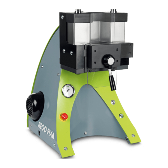
Page 12: Overview Illustration / Components
Overview Illustration / Components Push button «OUT» With this push button, the process «unclamp» is activated and a light starts to flash. In the start position «OUT», the green light of the push button is steadily on. Push button «IN» With this push button, the process «clamp»... -
Page 13: Identification Plate
1126 11 19 2.6 A 2019 11 600 W 2019 11 Use only with powRgrip systems licensed by REGO-FIX rego-fix.com Information: www.powRgrip.ch or www.abnox.com Information on the identification plate / / 1. Type of the machine / / 2. Article number with modification index / / 3. -
Page 14: Technical Data
Technical Data Indication PGU 9500 E PGU 9500 A PGU 9500 J Unit Gear pump External gear Delivery rate per rev. Delivery rate Litre / min. Tank Litre Hydraulic Oil HLP ISO VG 32 PG size Hydraulic operating pressure clamp and unclamp PG 6 PG 10 PG 15... -
Page 15: Packaging And Transport
Packaging and Transport The system will be prepared and packed by ABNOX Ltd. for transport to the customer «first destination». The packaging unit should not be exposed to any more loads. The packaging as well as its content should be protected against any influences of humidity. The transport as well as the storage temperature must be between –... -
Page 16: Definition Of Interface
Definition of Interface Pos. 1 | Inlet The gear pump is powered by an electric motor. The connection is placed on the back of the unit. The socket type KD 14.1101.151 with fuse and main switch is included in the scope of supply. Connection power cord: Socket IEC 60320-1 / C14 for appliance class 1 with safety connection (2P+E). -
Page 17: First Installation
First Installation / / The system has been tested for leaks and functions with hydraulic oil before delivery / / Before the first installation can be started, the system must be unpacked completely NOTE Check if all hoses and screws are properly tightened (leak proof). / / The enclosed power cord is needed to operate the system. -
Page 18: Insert Of The Clamping Inserts Pg 06, Pg 10, Pg 15, Pg 25 Or
Insert of the Clamping Inserts PG 06, PG 10, PG 15, PG 25 or PG 32 Close and lock door. The door handle must be in the locked vertical position, if not, an error will occur. Press the push button «OUT». The clamping unit runs automatically to the start position «unclamp». -
Page 19: Operating
Operating Clamping a Tool Press push button «IN». The clamping unit runs automatically to start position «IN». Open door of the powRgrip clamping unit by turning locking lever into horizontal position. ® Insert powRgrip tool holder with collet and cutting tool into the powRgrip clamping unit. -
Page 20: Unclamping A Tool
Clean and degrease tool Before clamping, clean and degrease collet and cutting tool. NOTE Clean tool holder; dirt and grease reduce clamping force, accuracy and life of the system. Clamping check Please visually check that the collet sits tightly against the tool holder face. NOTE There must be no gap between collet and tool holder. -
Page 21: Exchange Of Clamping Insert
Exchange of Clamping Insert Press push button «OUT». Wait until starting position «OUT» is reached. Open door. Turn locking lever into horizontal position. Take hold of the clamping insert on the foldout part and pull it out of the clamping unit, if necessary with the help of the enclosed pull out tool. -
Page 22: Trouble Shooting, Fault Elimination
Trouble Shooting, Fault Elimination The PGU 9500 clamping unit detects and signals the following faults: Only specially instructed and trained personnel are allowed to eliminate all below NOTE described faults. NOTE For constructions diagrams and drawings see chapter 16. Both buttons are blinking red: Faults Possible cause / elimination Comments... -
Page 23: Operating- And Working Material (Eu Safety Data Sheet)
PGU clamping unit cannot detect and signal the following faults: Faults Possible cause / elimination Comments Proximity switch for clamping Check pressure gauge if pressure Machine builds up wrong pressure. insert is broken or in the wrong is reached. position. Tools cannot be unclamped nor Defective or dirty tool holder. -
Page 24: Maintenance Plan
11.1 Maintenance Plan The indicated maintenance intervals refer to a single-shift operation. The maintenance intervals are shortened when the system is used at higher levels, i.e. by several-shift operation. Additional negative influences such as dusty and dirty work surroundings have to be considered. When What Specially instructed... -
Page 25: Control Of Oil Level
11.3.3 Control of Oil Level Measurement rod Minimum mark for oil level Maximum mark for oil level NOTE The oil level has to within the two marks (min & max). If not: add or remove oil! Insert oil measure stick in to filler neck and screw it on. -
Page 26: Powrgrip Cleaning Instructions
13. powRgrip Cleaning Instructions ® Insert cleaning paper into the Bend paper over and wrap around Hold paper with thumb. slot of the taper cleaner from the taper cleaner. the front. Allow enough paper to cover the whole width of the slot. Push down towards the flange until completely seated. -
Page 27: Technical Data Powrgrip
14. Technical Data powRgrip ® 14.1 Presetting Range of powRgrip Collets ® PG 6 / -CF PG 6-S PG 10 / -CF PG 10-S PG 15 / -CF / TW PG 15-S PG 15-L** PG 25 / -CF L [mm] L [mm] L [mm] L [mm]... - Page 28 PG 25-S PG 25-L** PG 32 / -CF / -CB PG 32-S PG 32-L** L [mm] L [mm] L [mm] L [mm] L [mm] [mm] [Inch] min. max. min. max. min. max. min. max. min. max. 0,2–1,0 – – – –...
-
Page 29: Maximum Presetting Range For Powrgrip ® Standard Collets And Pg-Cf Collets
14.2 Maximum presetting Range for powRgrip Standard Collets ® and PG-CF Collets Sizes PG 6 PG 10 PG 15 PG 25 PG 32 L2 max. 26,5 40,5 L2: maximum depht (without stop screw) 14.3 Presetting Range of PG-TAP Collets with Internal Square Dimensions [mm/inch] PG 15-TAP [mm] PG 25-TAP [mm]... -
Page 30: Spare Parts
15. Spare Parts Operating manual PGU 9500... - Page 31 Part No. Pos. Description Pcs. Serial No. Serial No. ≤1130 ≥1131 manometer PGU 9500 0004260 0004260 door lever 8771200 8771200 push-button «OUT» 0005301 0008635 push-button «IN» 0005302 0008634 emergency stop switch 0004125 0008633 safety switch 0004120 0004120 rocker switch 0004124 0004124 hydraulic hose to manometer 0004443...
-
Page 32: Drawings And Diagrams
16. Drawings and Diagrams 16.1 Diagram powRgrip Clamping Unit PGU 9500 E, A and J ® Operating manual PGU 9500... -
Page 33: Hydraulic Diagram Powrgrip Clamping Unit Pgu 9500 E, A And J
16.2 Hydraulic Diagram powRgrip Clamping Unit PGU 9500 E, A and J ® Operating manual PGU 9500... -
Page 34: Electric Diagram Powrgrip Clamping Unit Pgu 9500 E, A And J
16.3 Electric Diagram powRgrip Clamping Unit PGU 9500 E, A and J ® Operating manual PGU 9500... - Page 35 Operating manual PGU 9500...
- Page 36 Operating manual PGU 9500...
-
Page 37: Conformity
17. Conformity EC declaration of conformity according to the EU Machinery Directive 2006 / 42 / EC, Annex II 1. A Manufacturer Person established in the Community authorised to compile the technical file Basil Schneiter ABNOX AG ABNOX AG Langackerstrasse 25 Langackerstrasse 25 CH –... -
Page 38: Eu Safety Data Sheet
18. EU Safety Data Sheet Hydraulic oil HLP ISO VG 32 Operating manual PGU 9500... - Page 39 Operating manual PGU 9500...
- Page 40 Operating manual PGU 9500...
Need help?
Do you have a question about the powRgrip PGU 9500 and is the answer not in the manual?
Questions and answers