Table of Contents
Advertisement
Advertisement
Table of Contents

Related Manuals for Rego-fix powRgrip PGU 9500

Summary of Contents for Rego-fix powRgrip PGU 9500
- Page 1 Translation of the original operating Manual ® powRgrip Clamping Unit PGU 9500...
- Page 2 Validity of this original operating manual: ® powRgrip Clamping Unit PGU 9500 E Art. Nr. 5680120 / 7610.95000 ® powRgrip Clamping Unit PGU 9500 A Art. Nr. 5680220 / 7610.95100 powRgrip® Clamping Unit PGU 9500 J Art. Nr. 5680320 / 7610.95200 Name of this documentation: Betriebsanleitung PGU 9500 englisch Version:...
- Page 3 • communicated otherwise to other persons than those stated above. • powRgrip ® is a registered trademark of REGO-FIX AG. • The powRgrip ® tool holding System is protected under international patents. The addresses below serve as future reference source.
-
Page 4: Table Of Contents
Table of Content Safety ....................... 1 General Safety Advises ....................1 Danger when Operating the System or Subassemblies ..........1 Safety and Protective Devices ..................1 Personal Protection and Organizational Measures ............1 Appropriate Use ......................2 Inappropriate Use ......................2 Danger and Information Symbols .................. -
Page 5: Safety
Safety 1.1 General Safety Advises The safety representative of the company has to guarantee the following conditions: • Only qualified personnel are assigned to operate the machines and devices. • The personnel should have the operating manual at their disposal inclusive of other product documents at any time when working with the machine. -
Page 6: Appropriate Use
1.5 Appropriate Use The system and components may only be used under the appropriate operating conditions. The system is to be used exclusively for clamping and unclamping of tools for machine tools according to the detailed specifications in the manual under section 2.1. All other use is considered inappropriate. -
Page 7: Danger By Hydraulic Energy
1.8 Danger by Hydraulic Energy • Only specially trained personnel with a good knowledge of and experience in hydraulics may only carry out working on the hydraulic equipment. • The system works with a pressure of max. 155 bar. Parts of the system such as pressure hoses and valves have to be depressurised before the start of any repairs. -
Page 8: Overview Of The System
Tool Holding System which has been released by one of the following companies: • ABNOX Ltd. - Switzerland • REGO-FIX AG - Switzerland WARNING For any other application of this system there is a danger of serious personal injury as well as mechanical damage. -
Page 9: Overview Illustration / Components
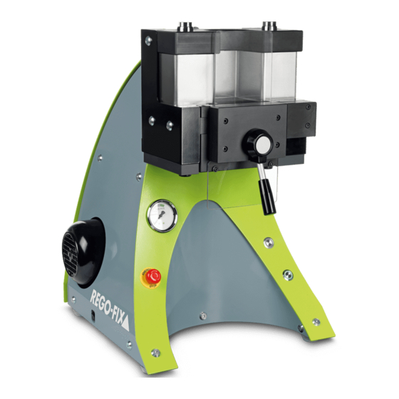
2.3 Overview Illustration / Components Pos. 1 Push button "unclamp" With this push button, the process "unclamp" is activated and a light starts to flash. In the start position "unclamp", the green light of the push button is steadily on. Pos. -
Page 10: Identification Plate
2.4 Identification Plate ® A plate (1) is mounted on the back of the powRgrip clamping unit. It contains important information used to identify the system. Information on the identification plate Pos. 1 Type of the machine Pos. 2 Article number with modification index Pos. -
Page 11: Technical Data
2.6 Technical Data Indication PGU 9500 E PGU 9500 A PGU 9500 J Unit Gear pump External gear Delivery rate per rev. Delivery rate Litre/min. Tank Litre Hydraulic Oil HLP ISO VG 32 Working pressure hydr. PG 06 clamp and unclamp Working pressure hydr. -
Page 12: Packaging And Transport
Packaging and Transport The system will be prepared and packed by ABNOX Ltd. for transport to the customer "first ® destination". The powRgrip clamping unit PGU 9500 E, A + J will be mounted onto a wooden frame and covered with a cardboard box. The packaging, mainly made of wood, cardboard and a plastic wrapping, is included in the delivery. -
Page 13: Definition Of Interface
Pos. 2. Outlet ® The hydraulic pressure is transferred to the powRgrip tool holding system by two hydraulic cylinders through a clamping insert. Clamping and unclamping force.……………………………………………….. see Chapter 2.6. ® Tool holder and collet powRgrip Tool Holding System by REGO-FIX AG... -
Page 14: First Installation
First installation • The system has been tested for leaks and functions with hydraulic oil before delivery. • Before the first installation can be started, the system must be unpacked completely. NOTE Check if all hoses and screws are properly tightened (leak proof). •... -
Page 15: Insert Of The Clamping Inserts Pg 06, Pg 10, Pg 15, Pg 25 Or
6.1 Insert of the clamping inserts PG 06, PG 10, PG 15, PG 25 or PG 32 Close and lock door (3). The door handle must be in the locked vertical position, if not, an error will occur. Press the push button "unclamp". The clamping unit runs automatically to the start position "unclamp". -
Page 16: Operating
Operating 7.1 Clamping a tool Press push button "clamp". The clamping unit runs automatically to start position "clamp" ® Open door of the powRgrip clamping unit by turning locking lever into horizontal position ® Insert powRgrip tool holder with collet and cutting tool into the ®... -
Page 17: Unclamping A Tool
Clamping a tool: NOTE Clamping without a tool will result in damage of the collet! Clamping length: NOTE For min./max. clamping length of tool shanks please refer to technical data sheet. 7.2 Unclamping a Tool Press push button "unclamp". The clamping unit runs automatically to start position "unclamp". -
Page 18: Exchange Of Clamping Insert
Exchange of clamping insert Press push button "unclamp". Wait until starting position "unclamp" is reached. Open door. Turn locking lever into horizontal position. Take hold of the clamping insert on the foldout part and pull it out of the clamping unit, if necessary with the help of the enclosed pull out tool. -
Page 19: Putting The System Out Of Operation
8.3 Putting the System out of Operation If the system is put out of operation and/or has to be transported, the following points must be observed: • Turn off main switch. • Disconnect power cord from main supply. • No hydraulic pressure is allowed in the system (check the pressure gauge). •... -
Page 20: Operating- Und Working Material (Eu Safety Data Sheet)
PGU clamping unit cannot detect and signal the following faults: Faults Possible cause / elimination Comments Machine builds up wrong Proximity switch for clamping insert is Check pressure gauge pressure broken or in the wrong position if pressure is reached Tools cannot be unclamped Defective or dirty tool holder nor clamped... -
Page 21: Maintenance And Service
Maintenance and Service In this chapter you will be informed about how to maintain this system. You will find an overview in which the maintenance and service plan is detailed. It is not mentioned in this chapter how to reassemble the system after any kind NOTE of error. -
Page 22: Service Instructions For Powrgrip® Clamping Unit
11.3 Service Instructions for powRgrip® Clamping Unit 11.3.1 Safety Danger of injury! ® Before beginning the service, the powRgrip clamping unit has to be turned off and has to be disconnected from the main electric supply! CAUTION 11.3.2 General Maintenance may only be done by qualified technicians or appropriately trained persons (responsible maintenance mechanic). -
Page 23: Spare Parts
Spare Parts... - Page 24 Stk. Art. Nr. Pos. Description Pcs. Art. no. manometer PGU 9500 0004260 door lever 8771200 push-button „unclamping“ 0005301 push-button „clamping“ 0005302 emergency stop switch 0004125 safty switch 0004120 rocker switch 0004124 hydraulic hose to manometer 0004443 hydraulic hose 0004442 ring bolt 8447100 proximity switch NO 0004281...
-
Page 25: Drawings And Diagrams
Drawings and Diagrams ® 14.1 Diagram powRgrip clamping unit PGU 9500 E, A and J... -
Page 26: Hydraulic Diagram Powrgrip Clamping Unit Pgu 9500 E, A Und J
® 14.2 Hydraulic Diagram powRgrip clamping unit PGU 9500 E, A und J... -
Page 27: Electric Diagram Powrgrip Clampin Unit Pgu 9500 E, A Und J
® 14.3 Electric Diagram powRgrip clampin unit PGU 9500 E, A und J... -
Page 29: Conformity
XXX MM YY - XXX MM YY Project number: PRJ-001121 Commercial name: powRgrip PGU 9500 Function: for clamp and unclamp tools of the powRgrip Tool Holding It is expressly declared that the machinery fulfils all relevant provisions of the following EU directives. -
Page 30: Eu Safety Data Sheet
EU Safety data sheet Hydraulic oil HLP ISO VG 32...
Need help?
Do you have a question about the powRgrip PGU 9500 and is the answer not in the manual?
Questions and answers