Table of Contents
Advertisement
Quick Links
USE AND CARE GUIDE
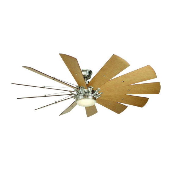
TRUDEAU LED 60 IN. CEILING FAN
Questions, problems, missing parts? Before returning to the store,
call Home Decorators Collection Customer Service
8 a.m. - 7 p.m., EST, Monday-Friday, 9 a.m. - 6 p.m., EST Saturday
1-800-986-3460
HOMEDEPOT.COM/HOMEDECORATORS
Visual instruction of how to install this fan:
Visit www.homedepot.com and enter either the Item or Model number to find
this fan and click the link of visual instruction in the product overview section.
THANK YOU
THANK YOU
Item #1001 693 774
#1001 693 781
#1004 671 399
Model # YG545A-BN
# YG545A-EB
# YG545A-MBK
Advertisement
Table of Contents

Related Manuals for Home Decorators Collection YG545A-BN


Summary of Contents for Home Decorators Collection YG545A-BN
- Page 1 USE AND CARE GUIDE TRUDEAU LED 60 IN. CEILING FAN Questions, problems, missing parts? Before returning to the store, call Home Decorators Collection Customer Service 8 a.m. - 7 p.m., EST, Monday-Friday, 9 a.m. - 6 p.m., EST Saturday 1-800-986-3460 HOMEDEPOT.COM/HOMEDECORATORS...
-
Page 2: Table Of Contents
Table of Contents Table of Contents ............Operation ..............Preparing the Transmitter ............Safety Information ............Learning Process ..............Operating Your Fan and Remote Control ....... Warranty ................. Warm/Cool Weather Operating Instructions ......Pre-installation .............. Care and Cleaning ............Specifications ................Tools Required ................. -
Page 3: Safety Information
The fan must be mounted with a minimum of 7 ft (2.1m) responsible for this declaration: clearance from the trailing edge of the blades to the floor. Model Number: YG545A-BN, YG545A-EB, YG545A-MBK Company Name: TAL INTERNATIONAL CORPORATION Avoid placing objects in the path of the blades. -
Page 4: Warranty
Warranty The manufacturer warrants the fan motor to be free from defects in workmanship and material present at time of shipment from the factory for a period of lifetime after the date of purchase by the original purchaser. The manufacturer warrants the light kit (excluding any glass), to be free from defects in workmanship and material present at time of shipment from the factory for a period of five years after the date of purchase by the original purchaser. -
Page 5: Hardware Included
Pre-Installation (continued) HARDWARE INCLUDED HARDWARE INCLUDED NOTE: Hardware not shown to actual size. Part Part Description Description Quantity Quantity Plastic wire nut Canopy mounting screw with lock washer (preassembled) Blade attachment screw and fiber washer Blade arm screw and lock washer Clevis pin (preassembled) Cotter pin (preassembled) Cross pin (preassembled) -
Page 6: Package Contents
Pre-Installation (continued) PACKAGE CONTENTS PACKAGE CONTENTS Part Part Description Description Quantity Quantity Part Part Description Description Quantity Quantity Mounting bracket (preassembled) Blade Canopy ring (preassembled) Blade arm Canopy Light kit mounting plate Hanger ball/downrod assembly 20 watt LED Light kit Coupling cover Glass shade Fan motor assembly... -
Page 7: Installation
Installation MOUNTING OPTIONS MOUNTING OPTIONS NOTE: You may need a longer downrod to maintain proper WARNING: To reduce the risk of fire, electric shock, or blade clearance when installing on a steep, sloped ceiling. The personal injury, mount the fan to an outlet box marked acceptable for fan support using the screws provided with the maximum angle allowable is 18°... -
Page 8: Assembly
Assembly Preparing the canopy Preparing the motor □ □ Remove the two collar setscrews (II) and remove the Remove the canopy ring (B) from the canopy (C). collar support plate (RR), keep the two collar setscrews (II) for future use and discard the collar □... -
Page 9: Hanging The Fan
Assembly — Hanging the Fan Hanging the fan to the mounting Installing the mounting bracket bracket to the electrical box WARNING: To reduce the risk of fire, electric shock or WARNING: The tab in the ring must rest in the groove of other personal injury, mount the fan only to an outlet box or the hanger ball/downrod assembly (D). - Page 10 Assembly — Hanging the Fan (continued) Making the electrical connections Ground WARNING: To avoid possible electrical shock, be sure conductor Neutral electricity is turned off at the main fuse box before wiring. Black White WARNING: Check to see that all connections are tight, including ground, and that no bare wire is visible at the wire nuts (except for the ground wire).
- Page 11 Assembly — Hanging the Fan (continued) Installing the canopy WARNING: Make sure the tab on the mounting bracket (A) properly sits in the groove in the hanger ball/downrod assembly (D) before attaching the canopy (C) to the mounting bracket (A) by turning the canopy (C) until it drops into place. WARNING: The locking slots of the canopy (C) are provided only as an aid to mounting.
-
Page 12: Attaching The Fan Blades
Assembly — Attaching the Fan Blades Attaching the blades to the Fastening the blade blade arms assemblies to the motor WARNING: NOTE: Your fan blades are reversible. Select the blade side To reduce the risk of personal injury, do not bend the blade arms (I) while installing, balancing the blades finish which best accentuates your decor. - Page 13 Assembly — Attaching the Fan Blades (continued) Attaching the decorative rod □ Rotate the decorative rods (G) onto the setscrew (WW) on the motor housing and firmly tightened. □ Insert the decorative rods (G) through the holes on the decorative rod holder (JJ). □...
-
Page 14: Installing The Light Kit
Assembly — Installing the Light Kit Attaching the light kit mounting Attaching the LED light kit plate to the mounting ring and glass shade □ Remove one of the three light kit mounting plate CAUTION: Before starting installation, disconnect the screws (MM) from the mounting ring (XX) and loosen power by turning off the circuit breaker or removing the fuse the other two screws. -
Page 15: Operation
Operation PREPARING THE TRANSMITTER Batteries will weaken with age and should be NOTE: replaced before leaking takes place as this will damage the remote control. Dispose of used batteries properly and keep them out of the reach of children. □ Remove the battery cover by pressing firmly on the arrow and sliding the cover off. - Page 16 Operation (continued) To clear all other remotes from your fan’s memory, use the steps below: □ Ensure AC power to the fan is OFF to begin the learning process. □ Slide the dip switch in the battery compartment to the "0" position.
-
Page 17: Operating Your Fan And Remote Control
Operation (continued) OPERATING YOUR FAN AND REMOTE CONTROL NOTE: The fan will store the last used speed setting for the next time it is turned on. NOTE: You must turn the fan on prior to using the speed or time functions. NOTE: On each start up of your ceiling fan, the fan blades will oscillate back and forth. -
Page 18: Warm/Cool Weather Operating Instructions
Operation (continued) Timer □ Pressing the timer buttons will automatically turn fan and light (if light is on) off after 2, 4, or 8 hours. When you activate the timer mode, the LED to the left of the time above the clock will illuminate. Disables timer Fan reverse button (Must be pushed when the fan is in operation) □... -
Page 19: Care And Cleaning
Care and Cleaning Do Do Do not Do not □ □ Check the support connections, brackets, and blade Use water when cleaning. Water could damage the motor, attachments twice a year. Make sure they are secure. or the wood, or possibly cause an electrical shock. Because of the fan’s natural movement, some □... - Page 20 Troubleshooting (continued) Problem Problem Solution Solution □ Do not connect the fan with wall mounted variable speed control(s). The remote control is not working. □ Make sure the frequency switches are set correctly. □ Reset the transmitter by going through the transmitter “LEARNING PROCESS”. □...
-
Page 21: Service Parts
Service Parts Part Part Description Description Part Part Description Description Mounting bracket (preassembled) Plastic wire nut Canopy ring (preassembled) Canopy mounting screw with lock washer (preassembled) Canopy Blade attachment screw and fiber washer Hanger ball/downrod assembly Blade arm screw and lock washer Coupling cover Clevis pin (preassembled) Fan motor assembly... - Page 22 Questions, problems, missing parts? Before returning to the store, call Home Decorators Collection Customer Service 8 a.m. - 7 p.m., EST, Monday-Friday, 9 a.m. - 6 p.m., EST Saturday 1-800-986-3460 HOMEDEPOT.COM/HOMEDECORATORS Retain this manual for future use.
Need help?
Do you have a question about the YG545A-BN and is the answer not in the manual?
Questions and answers