
Related Manuals for RKI Instruments CO-04


Summary of Contents for RKI Instruments CO-04
- Page 1 CO-04 Operator’s Manual Part Number: 71-0600 Revision: P1 Released: 8/9/22 RKI Instruments, Inc. www.rkiinstruments.com...
- Page 2 User Mode bump test or does not respond appropriately, as defined by the user, in Measuring Mode. For more information about bump test and calibration requirements, see IEC 60079-29-2. 2 • CO-04 Operator’s Manual...
-
Page 3: Table Of Contents
Turning On the CO-04 ........ - Page 4 Turning the Key Tone On/Off (KEY.TONE) ........65 4 • CO-04 Operator’s Manual...
- Page 5 User Mode Zero Suppression (ZSUP.DSP) ........88 CO-04 Operator’s Manual • 5...
- Page 6 La substitution de composants peut nuire à la sécurité intrinsèque. Pour éviter l'inflammation d'une atmosphère dangereuse, les batteries ne doivent être remplacées ou chargées que dans une zone non dangereuse. Non testé dans des atmosphères enrichies en oxygène (plus de 21%). 6 • CO-04 Operator’s Manual...
-
Page 7: Chapter 1: Introduction
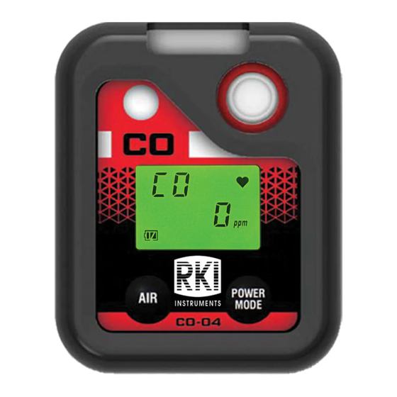
Chapter 1: Introduction Overview This chapter briefly describes the CO-04 gas monitor. This chapter also describes the CO-04 Operator’s Manual (this document). Table at the end of this chapter lists the specifications for the CO-04. About the CO-04 Using an advanced detection system, the CO-04 personal gas monitor detects the presence of carbon monoxide (CO). -
Page 8: Specifications
AVERTISSEMENT: Le modèle CO-04 détecte les niveaux élevés de monoxyde de carbone qui peuvent être dangereux ou mettre la vie en danger. Lorsque vous utilisez le CO-04, vous devez suivre les instructions et les avertissements de ce manuel pour assurer un fonctionnement correct et en toute sécurité de l'appareil et pour réduire les risques de blessures. - Page 9 Table 2: CO-04 Specifications • ATEX: Certificate Number DEKRA 19ATEX0097 II 1G Ex ia IIC T4 Ga (with alkaline batteries) II 1G Ex ia IIC T3, Ga (with Ni-MH batteries) Safety/ • IECEx: Certificate Number IECEx DEK 19.0059 Regulatory Ex ia IIC T4 Ga (with alkaline batteries) Ex ia IIC T3 Ga (with Ni-MH batteries) •...
-
Page 10: About This Manual
About this Manual The CO-04 Operator’s Manual uses the following conventions for notes, cautions, and warnings. NOTE: Describes additional or critical information. CAUTION: Describes potential damage to equipment. WARNING: Describes potential danger that can result in injury or death. 10 • Chapter 1: Introduction... -
Page 11: Chapter 2: Description
A digital LCD (liquid crystal display) is visible through a clear plastic window in the top case. The LCD shows the gas reading. The LCD also shows information for each of the CO-04’s operating modes. -
Page 12: Control Buttons
Maintenance, or Gas Select Mode. Vibrator A vibrating motor inside the CO-04 case vibrates for gas alarms and unit malfunctions. NOTE: If STEALTH is set to ON, the vibrator only functions when VIB in the STEALTH Gas Select Mode item is set to ON (see page 96). -
Page 13: Sensor
Batteries 2 AAA batteries (alkaline or Ni-MH) power the CO-04. At 25°C alkaline batteries will last at least 9,000 hours (375 days) and Ni-MH batteries will last at least 6,000 hours (250 days). The battery icon in the upper right of the LCD shows remaining battery life. -
Page 14: Standard Accessories
Alligator Clip Closed Open Figure 2: Alligator Clip Protective Rubber Boot A protective rubber boot is installed over the CO-04. Side Front Figure 3: Rubber Boot 14 • Chapter 2: Description CO-04 Operator’s Manual... -
Page 15: Optional Accessories
Optional Accessories Belt Clip The belt clip installs to 2 spring bars on the rear case and is used to easily clip the CO-04 onto a belt. Belt Clip Figure 4: Belt Clip Wrist Strap The wrist strap connects to a feature on the back case. -
Page 16: Chapter 3: Measuring Mode
Measuring Mode. Start Up This section explains how to start up the CO-04, get it ready for operation, and turn it off. Turning On the CO-04 To illustrate certain functions, the following description of the CO-04 start up sequence assumes that the following items in User Mode are turned on: LUNCH, CAL.RMDR, and BP.RMDR in... - Page 17 Buzzer sounds double pulsing None tone tone Action • Option A, Perform The CO-04 cannot be used • Option A, Perform calibration: Press and until a successful calibration is calibration: If you want to release POWER MODE to performed. Press and release...
- Page 18 Buzzer sounds double pulsing None tone tone Action • Option A, Perform bump The CO-04 cannot be used • Option A, Perform bump test: Press and release until a successful bump test is test: If you want to enter POWER MODE to enter performed.
- Page 19 8. If ID DISP is set to ON (factory setting is OFF, see page 88), the User ID Screen appears for a few seconds, followed by the Station ID Screen. USER U_ID_001 S_ID_001 CO-04 Operator’s Manual Chapter 3: Measuring Mode • 19...
- Page 20 9. If the CO-04 experiences a sensor failure during start up, a screen indicating that the sensor failed appears and the buzzer sounds a double pulsing tone once per second. FAIL SENSOR You cannot acknowledge the failure and continue to Measuring Mode. Replace the failed sensor as soon as possible.
-
Page 21: Performing A Demand Zero
KEY.TONE is set to ON in User Mode). 4. Continue to hold AIR until the LCD prompts you to release it. The CO-04 sets the fresh air reading. Start up is complete and the unit is now ready for monitoring. -
Page 22: Measuring Mode Operation
(see page 63). Monitoring an Area 1. Start up the CO-04 as described above in “Start Up” on page 16. It is now in Measuring Mode. 2. The instrument displays the CO reading. 3. Take the CO-04 to the monitoring area. -
Page 23: Alarms
Alarm Indications The CO-04 buzzer sounds an alarm, the LED flashes, and the vibrator pulses when any sort of alarm condition or failure occurs. If the CO-04 is operating in Stealth Mode, the buzzer does not sound and the vibrator’s operation depends on the VIB setting in Gas Select Mode’s STEALTH item. - Page 24 • Alarm LED flashes once per second System Failure • FAIL SYSTEM and an error code Double pulsing tone appear on the LCD sounds once per second • Alarm LED flashes once per second 24 • Chapter 3: Measuring Mode CO-04 Operator’s Manual...
-
Page 25: Responding To Alarms
AVERTISSEMENT: Un dépassement de la plage peut indiquer une concentration extrême en monoxyde de carbone ou une concentration en explosif. Confirmez la concentration de gaz avec un CO-04 différent ou avec un autre dispositif de détection de gaz. 1. Follow your established procedure for an extreme gas condition. - Page 26 “Replacing the Batteries (Alkaline or Ni-MH)” on page 70. The CO-04 is fully functional during a low battery warning. However, only a couple of days of operating time remain. The amount of time depends on LCD backlight use and alarm frequency.
- Page 27 FLASH memory failure Temperature sensor failure 3. If the error code is anything but 031, the instrument cannot be used. Contact RKI Instruments, Inc. as soon as possible. If the error code is 031, press and release POWER MODE to continue into Measuring Mode if the instrument must be used temporarily.
-
Page 28: Data Logging
The data logging capacity depends on how often the CO-04 stores data and how often the CO-04 is turned on and off. The table below illustrates how much data logging time is available for the various interval times. -
Page 29: Chapter 4: Display Mode
• To change a flashing parameter, press and release AIR. To reverse the movement in a list (ie. from down to up or vice versa): a. Press and hold AIR. b. Immediately press POWER MODE and then release both buttons. CO-04 Operator’s Manual Chapter 4: Display Mode • 29... -
Page 30: Peak Screen (Peak)
CO-04 is turned off. The lunch break feature enables the CO-04 to save the peak reading when it is turned off so it can continue with the same peak when it is turned on again (see page 16). -
Page 31: Twa Screen (Twa)
Maintenance Mode is set to ON (factory setting is OFF). Use this screen to select a user ID from the 128 user IDs that are stored in the CO-04’s memory. Before a user ID is selected on a brand new instrument, the user ID is “----------”. The factory- installed user IDs have a “U_ID_XXX”... -
Page 32: Station Id Screen (Stn Id)
Maintenance Mode is set to ON (factory setting is OFF). Use this screen to select a station ID from the 128 station IDs that are stored in the CO-04’s memory. Before a station ID is selected on a brand new instrument, the station ID is “----------”. -
Page 33: Last Successful Calibration Date (Cal.data)
2. Press AIR to enter the BP.DATA screen. The date of the last successful bump test displays. 2019 10.24 BP .DATA 3. When you are done viewing the last bump test date, press and release POWER MODE to return to the BP.DATA screen in Display Mode. CO-04 Operator’s Manual Chapter 4: Display Mode • 33... -
Page 34: Date/Time Screen (Date)
1. After entering Display Mode, press and release POWER MODE until the ALARM--P screen sequence appears. DISP DISP DISP ALARM-P YES / AIR NO /MODE 2. Press and release AIR. The Full Scale Setting screen appears. 34 • Chapter 4: Display Mode CO-04 Operator’s Manual... -
Page 35: Adjusting The Buzzer Volume (Buzz.vol)
2. Press and release AIR. The current setting flashes. 3. Use AIR to display the desired setting. 4. Press and release POWER MODE to save the setting and return to the BUZZ.VOL item in Display Mode. CO-04 Operator’s Manual Chapter 4: Display Mode • 35... -
Page 36: Chapter 5: User Mode And Calibration
Chapter 5: User Mode and Calibration Overview This section describes the CO-04 in User Mode. See Table 8 below for a list of the items found in User Mode, the page that the item’s instructions can be found on, and a short description of the item. - Page 37 BP.DATA screen does not appear in Display Mode. BP.INT How often the instrument needs to be bump tested. (page 59) Options: 0 - 30 days (factory setting is 30 days) CO-04 Operator’s Manual Chapter 5: User Mode and Calibration • 37...
- Page 38 Options: 0 - 255 seconds or OFF. The factory setting is 30 seconds. KEY.TONE (page 65) ON (factory setting): Buzzer sounds when button is pressed. OFF: Buzzer does not sound when button is pressed. 38 • Chapter 5: User Mode and Calibration CO-04 Operator’s Manual...
-
Page 39: Entering User Mode
WARNING: The CO-04 is not in operation as a gas detector while in User Mode. 1. Take the CO-04 to a non-hazardous location and turn it off if it is on. 2. Press and hold AIR, then press and hold POWER MODE. When you hear a beep, release the buttons. -
Page 40: Tips For Using User Mode
Immediately press POWER MODE and then release both buttons. • To exit an entered item without saving a change, press and hold AIR and POWER MODE for a few seconds. 40 • Chapter 5: User Mode and Calibration CO-04 Operator’s Manual... -
Page 41: Performing A Bump Test (Bump)
2. Confirm that the regulator knob is turned all the way clockwise. Screw the 0.25 LPM fixed flow regulator onto the calibration cylinder. 3. Install the calibration cup onto the CO-04. Be sure the calibration cup is installed in the correct direction and that it is pushed on all the way. - Page 42 10. At the end of the countdown, the instrument analyzes the results. Follow the flow chart to determine the bump test outcome. Bump test passed? A-CAL On? (default is on) Calibration passed? Figure 6: Bump Test Flow Chart 42 • Chapter 5: User Mode and Calibration CO-04 Operator’s Manual...
-
Page 43: Performing A Calibration (Gas Cal)
6. Use AIR to scroll to START and press and release POWER MODE press and release POWER MODE to enter Measuring Mode. to enter Measuring Mode. 7. Calibrate the CO-04 as soon as possible. CO-04 Operator’s Manual Chapter 5: User Mode and Calibration • 43... - Page 44 8. Use AIR to scroll to START and press 8. Use AIR to scroll to START and press and release POWER MODE to enter and release POWER MODE to enter Measuring Mode. Measuring Mode. 44 • Chapter 5: User Mode and Calibration CO-04 Operator’s Manual...
- Page 45 • To fully calibrate the sensors, you must do a fresh air adjustment (AIR CAL) and a span adjustment (A-CAL or E-CAL). • The CO-04 can be calibrated using either A-CAL or E-CAL depending on the setting of the E- CAL User Mode item.
- Page 46 • Non-absorbent tubing • Calibration cup 1. Confirm that the CO-04’s calibration gas value matches the concentration listed on the calibration gas cylinder as described on page 53. 2. Confirm that the regulator knob is turned all the way clockwise. Screw the 0.25 LPM fixed flow regulator onto the calibration cylinder.
- Page 47 3. Install the calibration cup onto the CO-04. Be sure the calibration cup is installed in the correct direction and that it is pushed on all the way. POW ER MODE Side View Front View 4. Use the tubing to connect the regulator to the inlet of the calibration cup (labeled “IN”).
- Page 48 AIR and POWER MODE together. 7. Turn the regulator knob counterclockwise to open the regulator. 8. Allow the gas to flow for 1 minute. 9. Press and release POWER MODE. 48 • Chapter 5: User Mode and Calibration CO-04 Operator’s Manual...
- Page 49 MAX .SPAN 4. Close the regulator. 5. Remove the calibration cup. 6. Press and release POWER MODE to enter Measuring Mode. CO-04 Operator’s Manual Chapter 5: User Mode and Calibration • 49...
- Page 50 2. Confirm that the regulator knob is turned all the way clockwise. Screw the 0.25 LPM fixed flow regulator onto the calibration cylinder. 3. Install the calibration cup onto the CO-04. Be sure the calibration cup is installed in the correct direction and that it is pushed on all the way.
- Page 51 If the reading never reaches 10% of the auto calibration value, press and release POWER MODE to fail the calibration. APLY 9. At the end of the countdown, the instrument makes the span adjustment. CO-04 Operator’s Manual Chapter 5: User Mode and Calibration • 51...
- Page 52 MAX .SPAN 4. Close the regulator. 5. Remove the calibration cup. 6. Press and release POWER MODE to enter Measuring Mode. 52 • Chapter 5: User Mode and Calibration CO-04 Operator’s Manual...
- Page 53 Limits on the calibration gas value are shown in the table below. Min. Cal. Max. Cal Channel Concentration Concentration Carbon Monoxide 15 ppm 2,000 ppm CO-04 Operator’s Manual Chapter 5: User Mode and Calibration • 53...
-
Page 54: Setting Calibration Parameters (Cal Set)
CAL .RMDR CAL.RMDR ON (factory setting): The CO-04 gives an indication at start up if it is due for calibration. The type of indication depends on the CAL.EXPD setting (see page 55). OFF: The CO-04 does not give an indication at start up if it is due for calibration. - Page 55 A successful calibration must be performed in order to use the instrument. NONE: The CO-04 gives an indication at startup that calibration is past due. It is not necessary to acknowledge the indication. If desired, press POWER MODE to enter User Mode and perform a calibration.
-
Page 56: Setting Bump Test Parameters (Bump.set)
The SETTING menu has 5 items: GAS.TIME, CHECK, CAL.TIME, A-CAL, and ESCAPE. 1. After entering the BUMP.SET menu, press AIR to scroll to SETTING. SETTING 2. Press and release POWER MODE. The GAS.TIME item appears. 56 • Chapter 5: User Mode and Calibration CO-04 Operator’s Manual... - Page 57 4. Press and release POWER MODE to save the setting and return to the CHECK item in the SETTING menu. 5. See “Exiting the SETTING Menu” on page 58 to return to BUMP.SET menu. CO-04 Operator’s Manual Chapter 5: User Mode and Calibration • 57...
- Page 58 CAL.TIME is set to 90 seconds and the GAS.TIME is set to 30 seconds, if the bump test fails, the CO-04 is only exposed to gas for an additional 60 seconds. The available values are 90 seconds (factory setting), and 120 seconds.
- Page 59 BP.RMDR ON: The CO-04 gives an indication at start up if it is due for bump testing. The type of indication depends on the BP.EXPD setting (see page 59). If the instrument is not due for bump testing, a check mark appears in the lower left corner of the LCD.
-
Page 60: Alarm Settings (Alarm--P)
A successful bump test must be performed in order to use the instrument. NONE: The CO-04 gives an indication at startup that a bump test is past due. It is not necessary to acknowledge the indication. If desired, press POWER MODE to enter User Mode and perform a bump test. - Page 61 SAVE-AP item in Gas Select Mode if you performed a SAVE-AP operation. 1. After entering the ALARM-P menu, press AIR to scroll to DEF.ALMP. DEF .ALMP CO-04 Operator’s Manual Chapter 5: User Mode and Calibration • 61...
-
Page 62: Updating The Lunch Break Setting (Lunch)
TWA and PEAK readings and the time in operation from the last time the CO-04 was used or start collecting new readings and reset the time in operation. 1. While in User Mode, press AIR to scroll to LUNCH. -
Page 63: Setting The Confirmation Beep And Non-Compliance Indicator (Beep)
OFF (factory setting): The CO-04 does not provide a confirmation alert or non-compliance indicator. LED: The CO-04’s LED double flashes as often as defined by the BEEP.INT parameter to verify that the instrument is operating. BUZZER: The CO-04’s buzzer double beeps as often as defined by the BEEP.INT parameter to verify that the instrument is operating. -
Page 64: Updating The Backlight Time (Bl Time)
1. While in User Mode, press AIR to scroll to BL TIME. BL TIME 2. Press and release POWER MODE. The current setting flashes. 3. Use AIR to display the desired setting. 64 • Chapter 5: User Mode and Calibration CO-04 Operator’s Manual... -
Page 65: Turning The Key Tone On/Off (Key.tone)
4. Press and release POWER MODE to save the setting and return to the DISP.SET item in User Mode. 5. See “Entering Measuring Mode (START)” on page 68 to enter Measuring Mode. CO-04 Operator’s Manual Chapter 5: User Mode and Calibration • 65... -
Page 66: Zero Suppression (Zero.sup)
5. See “Entering Measuring Mode (START)” on page 68 to enter Measuring Mode. Setting the Date/Time (DATE) 1. While in User Mode, place the cursor next to DATE. DATE 66 • Chapter 5: User Mode and Calibration CO-04 Operator’s Manual... -
Page 67: Turning The Password On/Off (Pass-W)
6. See “Entering Measuring Mode (START)” on page 68 to enter Measuring Mode. Turning the Password On/Off (PASS-W) ON: The CO-04 prompts you for a password when you enter User Mode. The factory-set password is 0405 but it can be changed. -
Page 68: Viewing The Rom/Sum (Rom/Sum)
4. See “Entering Measuring Mode (START)” on page 68 to enter Measuring Mode. Entering Measuring Mode (START) 1. While in User Mode, press AIR to scroll to START. START 2. Press and release POWER MODE. The instrument begins its warmup sequence. 68 • Chapter 5: User Mode and Calibration CO-04 Operator’s Manual... -
Page 69: Chapter 6: Maintenance
Chapter 6: Maintenance Overview This chapter describes troubleshooting procedures for the CO-04. It also includes procedures for replacing the batteries and replacing various consumable parts. WARNING: RKI Instruments recommends that service, calibration, and repair of RKI gas detectors be performed by personnel properly trained for this work. Replacing the sensor and other parts with original equipment does not affect the intrinsic safety of the instrument. -
Page 70: Replacing The Batteries
être remplacée que dans une zone non dangereuse. WARNING: Use only Duracell MN2400 or PC2400 or Eneloop BK-4MCC batteries to maintain the QPS classification of the CO-04. Use of other batteries will void the QPS classification and may void the warranty. Do not mix old/new or different types of batteries. - Page 71 4. Remove the battery cover. 5. Remove the old batteries. NOTE: New batteries must be installed within 5 minutes to avoid having to reset the date/time. Battery Cover Figure 9: Battery Cover Removal CO-04 Operator’s Manual Chapter 6: Maintenance • 71...
- Page 72 WARNING: To prevent ignition of a hazardous atmosphere, batteries must only be charged in an area known to be nonhazardous. 1. Remove the batteries from the CO-04 as described in Step 1 - Step 5 on page 70. 2. Install the Ni-MH batteries in the charger. See the battery charger’s manual for charging instructions.
-
Page 73: Replacing The Charcoal Filter
Replacing the Charcoal Filter 1. Verify that the CO-04 is off. 2. Remove the rubber boot, if installed. 3. Use a small Phillips screwdriver to unscrew the 4 screws that attached the front case to the rear case. Screw, 4x Figure 11: Unscrewing Case Screws 4. - Page 74 11. Reinstall the front case to the rear case. 12. Reinstall the 4 screws that were removed in Step 3. 13. Reinstall the rubber boot, if being used. 74 • Chapter 6: Maintenance CO-04 Operator’s Manual...
-
Page 75: Replacing The Hydrophobic Filter
Replacing the Hydrophobic Filter 1. Verify that the CO-04 is off. 2. Remove the rubber boot, if installed. 3. Use a small Phillips screwdriver to unscrew the 4 screws that attached the front case to the rear case. Screw, 4x Figure 14: Unscrewing Case Screws 4. - Page 76 14. Reinstall the front case to the rear case. 15. Reinstall the 4 screws that were removed in Step 3. 16. Reinstall the rubber boot, if being used. 76 • Chapter 6: Maintenance CO-04 Operator’s Manual...
-
Page 77: Replacing The Sensor
Replacing the Sensor 1. Verify that the CO-04 is off. 2. Remove the rubber boot, if installed. 3. Use a small Phillips screwdriver to unscrew the 4 screws that attached the front case to the rear case. Screw, 4x Figure 17: Unscrewing Case Screws 4. - Page 78 9. Reinstall the front case to the rear case. 10. Reinstall the 4 screws that were removed in Step 3. 11. Reinstall the rubber boot, if being used. 12. Calibrate the CO response as described on page 43. 78 • Chapter 6: Maintenance CO-04 Operator’s Manual...
-
Page 79: Chapter 7: General Parts List
Operator’s Manual, 04 Series Datalogging Program 71-0526 Operator’s Manual, 04 Series Setup Program 71-0600 Operator’s Manual, CO-04 (this document) 81-0064RK-01 Calibration cylinder, 50 ppm CO in air, 34 liter steel 81-0064RK-03 Calibration cylinder, 50 ppm CO in air, 103 liter... - Page 80 Part Number Description 81-1146 Calibration cup 81-CO04C-LV Calibration kit: 34 liter steel cylinder of 50 ppm CO in N , regulator, tubing, cali- bration cup, case ESR-A13P-CO Carbon monoxide (CO) sensor 80 • Chapter 7: General Parts List CO-04 Operator’s Manual...
-
Page 81: Appendix A: Maintenance Mode
AIR. A.ZERO (page 87) ON: The CO-04 asks if you want to perform a fresh air adjustment at the end of the startup sequence. OFF (factory setting): The CO-04 does not ask if you want to perform a fresh air adjustment at the end of the startup sequence. -
Page 82: Entering Maintenance Mode
WARNING: The CO-04 is not in operation as a gas detector while in Maintenance Mode. 1. Take the CO-04 to a non-hazardous location and turn it off if it is on. 2. Press and hold AIR, then press and hold POWER MODE. You will hear a beep after one second. -
Page 83: Tips For Using Maintenance Mode
Immediately press POWER MODE and then release both buttons. • To exit an entered item without saving a change, press and hold AIR and POWER MODE for a few seconds. CO-04 Operator’s Manual Appendix A: Maintenance Mode • 83... -
Page 84: Performing A Calibration (Gas Cal)
1. Confirm that the regulator knob is turned all the way clockwise. Screw the 0.25 LPM fixed flow regulator onto the calibration cylinder. 2. Install the calibration cup onto the CO-04. Be sure the calibration cup is installed in the correct direction and that it is pushed on all the way. -
Page 85: Sensor/Battery Replacement Date (Sen.date)
5. Turn the regulator knob clockwise to close the regulator. 6. Unscrew the regulator from the calibration cylinder. 7. Remove the calibration cup from the CO-04. 8. Store the calibration kit in a safe and convenient place. 9. Press and release POWER MODE to return to the GAS.TEST item in Maintenance Mode. -
Page 86: Performing A Bump Test (Bump)
See “Performing a Bump Test (BUMP)” on page 41 for a description of the BUMP item. Setting Alarms to Latching or Self-Resetting (LATCH) ON (factory setting): The CO-04 remains in alarm until the alarm condition passes and POWER MODE is pressed. -
Page 87: Turning The Demand Zero Function On/Off (D.zero)
5. See “Entering Measuring Mode (START)” on page 92 to enter Measuring Mode. Turning the Auto Zero Function On/Off (A.ZERO) ON: The CO-04 asks if you want to perform a fresh air adjustment at the end of the startup sequence. -
Page 88: Turning The Id Display Function On/Off (Id Disp)
OFF (factory setting): Zero suppression item does not appear in User Mode. The zero suppression item is always available in Maintenance Mode. It is not normally necessary to have the zero suppression item appear in User Mode. Contact RKI Instruments before turning this setting on. 88 • Appendix A: Maintenance Mode CO-04 Operator’s Manual... -
Page 89: User Mode Zero Follower (Zflw.dsp)
5. Repeat Step 3 and Step 4 to enter the month, day, hours, and minutes settings. The date and time are saved and the instrument returns to the DATE item in Maintenance Mode. 6. See “Entering Measuring Mode (START)” on page 92 to enter Measuring Mode. CO-04 Operator’s Manual Appendix A: Maintenance Mode • 89... -
Page 90: Turning The Password On/Off (Pass-W)
Turning the Password On/Off (PASS-W) ON (factory setting): The CO-04 prompts you for a password when you enter Maintenance Mode. The factory-set password is 0400 but it can be changed. OFF: No password is required to enter Maintenance Mode. 1. While in Maintenance Mode, press AIR to scroll to PASS-W. -
Page 91: Viewing The Rom/Sum (Rom/Sum)
Performing a default operation in Maintenance Mode returns all parameters to their RKI factory settings. 1. While in Maintenance Mode, press AIR to scroll to M.DEF. M .DEF 2. Press and release POWER MODE. M .DEF YES .MODE NO .AIR CO-04 Operator’s Manual Appendix A: Maintenance Mode • 91... -
Page 92: Entering Measuring Mode (Start)
5. See “Entering Measuring Mode (START)” on page 92 to enter Measuring Mode. Entering Measuring Mode (START) 1. While in Maintenance Mode, press AIR to scroll to START. START 2. Press and release POWER MODE. The instrument begins its warmup sequence. 92 • Appendix A: Maintenance Mode CO-04 Operator’s Manual... -
Page 93: Appendix B: Gas Select Mode
Appendix B: Gas Select Mode Overview This appendix describes the CO-04 in Gas Select Mode. The CO-04 is factory-set to suit most applications. Update settings in Gas Select Mode only if required for your specific application. A description of the Gas Select Mode items is shown in Table 14 below. -
Page 94: Tips For Using Gas Select Mode
RKI default regardless of if a SAVE-AP operation was performed. 1. While in Gas Select Mode, press AIR to scroll to SAVE-AP. SAVE - AP 94 • Appendix B: Gas Select Mode CO-04 Operator’s Manual... -
Page 95: Turning The Calibration Max Span On/Off (Max.span)
5. See “Exiting Gas Select Mode (START)” on page 96 to enter Measuring Mode. Turning Calibration Max Span On/Off (MAX.SPAN) ON: After a passed calibration, the CO-04 displays the response reading’s maximum adjustment. A maximum span of 100 ppm indicates that the reading could have been adjusted up to 100 ppm. -
Page 96: Stealth And Vibrator Settings (Stealth)
Exiting Gas Select Mode (START) 1. While in Gas Select Mode, press AIR to scroll to START. START 2. Press and release POWER MODE. The instrument begins its warm-up sequence. 96 • Appendix B: Gas Select Mode CO-04 Operator’s Manual... -
Page 97: Warranty
Warranty RKI Instruments, Inc. warrants the CO-04 sold by us to be free from defects in materials, workmanship, and performance for a period of three years from the date of shipment from RKI Instruments, Inc. This includes the instrument and the original sensor. Replacement parts are warranted for 1 year from the date of their shipment from RKI Instruments, Inc.
Need help?
Do you have a question about the CO-04 and is the answer not in the manual?
Questions and answers