Table of Contents
Advertisement
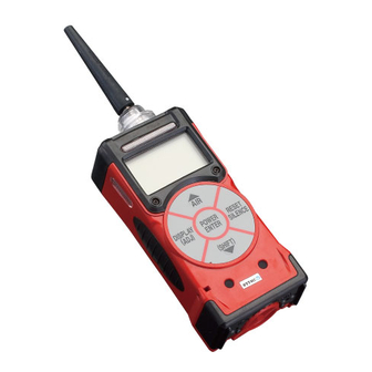
Quick Reference Guide For Model GX-2003
Note: Turn on and adjust the GX-2003 gas monitor in a known fresh air area.
1. Turning the GX-2003 ON
a. Attach the rubber nozzle or sample hose to the GX-2003's
quick connect inlet fitting.
b. Attach probe to hose as necessary.
c. To turn on the GX-2003, press and briefly hold down the
POWER/ENTER button until you hear a beep. The GX-2003
will begin its warm up sequence, and display the following
screens:
USER/STATION ID
• The USER/STATION ID screen displays for a few
seconds.
CAL TIME REMAINING (factory default setting)
• If the instrument is overdue for calibration the GX-2003
displays: CAL DATE PAST, CAL IS REQUIRED. Press
the RESET SILENCE button to continue.
• Calibration should be performed as soon as possible.
DATE/TIME/BATTERY LEVEL
• This screen displays the current date, time and an
indication of how much battery charge remains. If the
battery icon is fully filled in black, then the batteries are
fully charged.
Note: Check battery level by observing the battery
icon on the LCD. If battery level is low, replace alkaline
batteries or recharge Ni-MH battery pack before use.
SENSOR FAILURE
• If the GX-2003 experiences a sensor failure during start
up, the LCD will indicate the failed sensor in brackets.
Example FAIL SENSOR <H2S>. To continue operation
press and release the RESET SILENCE button to
acknowledge the failure. Gas readings for that sensor will
be replaced by XXX's.
• It is necessary to replace the sensor and recalibrate
before the GX-2003 is used.
2. Measuring Mode Screen
a. After warm-up the GX-2003 will display the following: CH4
0%LEL, OXY 20.9 VOL%, H2S 0.0ppm, CO 0ppm.
b. If the unit is not displaying fresh air values as above, it is
necessary to perform a Demand Zero.
Advertisement
Chapters
Table of Contents

Related Manuals for RKI Instruments GX-2003


Summary of Contents for RKI Instruments GX-2003
- Page 1 Quick Reference Guide For Model GX-2003 Note: Turn on and adjust the GX-2003 gas monitor in a known fresh air area. 1. Turning the GX-2003 ON a. Attach the rubber nozzle or sample hose to the GX-2003’s quick connect inlet fitting.
- Page 2 5. Flow Integrity Test a. Place finger over end of probe or rubber tip, the GX-2003 should go into flow fail in a few seconds. b. Press the RESET button to restart the pump. c. If the instrument fails to indicate flow failure, check probe and hose connections for leaks.
- Page 3 Model GX-2003 Operator’s Manual Part Number: 71-0089RK Revision: D Released: 3/26/07 www.rkiinstruments.com...
- Page 4 Warranty RKI Instruments, Inc., warrants the Model GX-2003 sold by us to be free from defects in materials, workmanship, and performance for a period of two years from the date of shipment from RKI Instruments, Inc. This includes the instrument and the original sensors.
-
Page 5: Table Of Contents
About the GX-2003 ........ - Page 6 Preparing for Calibration ....... . . 39 Calibrating the GX-2003........39 Adjusting the LCD Contrast.
- Page 7 Updating the LCD Contrast Setting ......66 Updating the GX-2003’s Serial Number..... . 66 Turning the User ID Function On or Off .
- Page 8 Calibrating the GX-2003 ........
-
Page 9: Chapter 1: Introduction
Chapter 1: Introduction Overview This chapter briefly describes the GX-2003. This chapter also describes the GX-2003 Operator’s Manual (this document). Table 1 at the end of this chapter lists the specifications for the GX-2003. About the GX-2003 Using an advanced detection system consisting of up to five gas... - Page 10 • CSA classified for Class I, Division I, Groups A, B, C, and D hazardous atmospheres WARNING: The Model GX-2003 detects oxygen deficiency, elevated levels of oxygen, combustible gases, carbon monoxide, and hydrogen sulfide, all of which can be dangerous or life threatening.
-
Page 11: Specifications
Specifications Table 1: GX-2003 Specifications Target Gas %LEL % Volume Oxygen (O Hydrogen Carbon Combustible Combustible Sulfide Monoxide (CO) (Methane (Methane Calibration Calibration Standard) Standard) Range 0-100% LEL 0 - 100% vol 0-40.0% vol 0-100 ppm 0-500 ppm (Increment) (1% LEL) (1% vol) (0.1 vol%) -
Page 12: About This Manual
Approximately 171(H) x 65(W) x 39(D) mm (5.6”H x 2.5”W x 1.5”D) and Weight Approximately 310 g (11 oz.) About this Manual The GX-2003 Operator’s Manual uses the following conventions for notes, cautions, and warnings. NOTE: Describes additional or critical information. CAUTION: Describes potential damage to equipment. -
Page 13: Chapter 2: Description
Holder Inlet Fitting Alarm Exhaust Array HC Filter Retainer Flow CO Filter Chamber Retainer Battery Cover DISPLAY RESET (ADJ) SILENCE (SHIFT) Control Buttons Buzzer Openings Figure 1: Components of the GX-2003, Front & Back GX-2003 Operator’s Manual Overview • 11... -
Page 14: Case
The battery cover release knob is also on the bottom. The battery cover and flow chamber are located on the back of the GX-2003. The inlet filter holder is located on the top of the GX-2003 case. -
Page 15: Sensors
Sensors The GX-2003 uses up to five sensors to monitor combustible gas, oxygen (O2), carbon monoxide (CO), and hydrogen sulfide (H simultaneously. The sensors are located inside the GX-2003 and are held in their sockets by the flow chamber. The sensors use different detection principles, as described below. -
Page 16: Lcd
• scrolls through the display and settings modes • enters instructions into the GX-2003’s microprocessor 1 The GX-2003’s alarms are user-adjustable. See “Chapter 6: Setup Mode” on page 58. Printed Circuit Boards The GX-2003 printed circuit boards analyze, record, control, store, and display the information collected. -
Page 17: Alarm Led Arrays
IrDA protocol. A computer’s infrared port or an IrDA/serial or IrDA/USB cable connected to a computer’s serial port can be used to download data saved by the GX-2003 to a computer using the GX- 2003 Downloading Software. See the downloading software operator’s manual for data logging and downloading instructions. -
Page 18: Pump
GX-2003 because of flow rate reduction. Flow Chamber The flow chamber is on the back of the GX-2003 and is held in place by three phillips screws. The flow chamber seals on the face of the sensors inside the GX-2003 and routes flow from the pump to the sensors to the exhaust port (also a part of the flow chamber). -
Page 19: Inlet Filter Holder
The filter holder is a clear plastic dome shaped piece on the top of the case. A male quick connect fitting is located on the inlet filter holder. This is the GX-2003’s inlet fitting. A cotton dust filter is inside the filter holder. The filter holder may be removed by turning it counterclockwise and pulling it away from the case. -
Page 20: Standard Accessories
Tapered Rubber Nozzle A cone shaped 4 inch long rubber nozzle is included with the GX-2003 as standard. It can be installed on the inlet fitting by pushing the larger end over it. -
Page 21: Sample Hose & 10 Inch Probe
Bar Hole Probe (Optional) An optional bar hole probe is available for the GX-2003. It is designed to be used when the GX-2003 is operated in Bar Hole Mode to check bar holes when tracking down underground gas pipe leaks (see “Chapter 4: Using the GX-2003 in Bar Hole Mode”... -
Page 22: Chapter 3: Using The Gx-203 In Normal Mode
While in Normal Mode, Display Mode and Calibration Mode are accessible. If a standard version of the GX-2003 is ordered, it is shipped with Bar Hole Mode and Leak Check Mode disabled so that the instrument only runs in Normal Mode when turned on. - Page 23 • Press and release the AIR button to continue accumulating time-weighted average (TWA), PEAK readings, and time in operation from the last time the GX-2003 was used. The short- term exposure limit [STEL] reading is reset each time the GX- 2003 is turned on.
- Page 24 If the battery icon is fully filled in black, then the batteries are at full charge. 8. If the GX-2003 experiences a sensor failure during start up, a screen indicating which sensor failed displays. In the example below, the H2S sensor has failed.
-
Page 25: Turning On The Gx-2003 In Normal With All Modes Active
Mode. See “Chapter 4: Using the GX-2003 in Bar Hole Mode” on page 45 for a description of Bar Hole Mode and “Chapter 5: Using the GX-2003 in Leak Check Mode” on page 52 for a description of Leak Check Mode. -
Page 26: Performing A Demand Zero, Normal Mode
1. Find a fresh-air environment. This is an environment free of toxic or combustible gasses and of normal oxygen content (20.9%). 2. Turn on the unit as described above in “Turning On the GX-2003, Normal Mode Only” or “Turning On the GX-2003 in Normal Mode With All Modes Active”. -
Page 27: Turning Off The Gx-2003, Normal Mode
GX-2003 beeps once every 15 minutes to confirm that it’s operating. Monitoring an Area 1. Start up the GX-2003 as described above in “Start Up, Normal Mode” on page 20 or “Turning On the GX-2003 in Normal Mode With All Modes Active”. It is now in Measuring Mode 2. -
Page 28: Combustible Gas Detection
If exposure to these compounds is suspected, verify the %LEL response on a known gas sample. • Although the GX-2003 CH4 channel is setup for and calibrated to methane (CH ), the combustible sensors will respond to other combustible gasses as well. -
Page 29: Measuring Mode, Alarms
Measuring Mode, Alarms This section covers alarm indications in Measuring Mode. It also tells you how to reset the GX-2003 after an alarm has occurred and how to respond to an alarm condition. NOTE: False alarms may be caused by radio frequency (RF) or electromagnetic (EMI) interference. -
Page 30: Alarm Indications
See “HC Range Screen” on page 32. The GX-2003 will sound an alarm, the unit will vibrate, and the LED arrays will flash when one of the target gas concentrations rises above the Alarm 1 level, or in the case of oxygen, falls below the Low Alarm setting for that gas. -
Page 31: Resetting And Silencing Alarms
*This alarm can also occur in Bar Hole Mode and Leak Check Mode Resetting and Silencing Alarms You can set the GX-2003’s gas alarms as latching or self-resetting alarms (see “Updating the Alarm Latching Setting” on page 62). • Self-resetting alarms (ALARM LATCHING set to OFF) -
Page 32: Responding To Alarms
2. Follow your established procedure for an increasing gas condition. 3. Reset the alarm using the RESET SILENCE button once the alarm condition has cleared. 4. Calibrate the GX-2003 as described in the calibration section of this manual. 30 • Measuring Mode, Alarms... -
Page 33: Display Mode
“Replacing or Recharging the Batteries” on page 76 The Model GX-2003 is fully functional during a low battery warning. However, only a limited amount of operating time remains, approximately 1 - 2 hours. The amount of time depends on how often the LCD backlight is used and how often the unit is responding to alarm conditions. -
Page 34: Hc Range Screen
Mode. HC Range Screen This screen displays only if your GX-2003 is equipped with both the catalytic % LEL combustible sensor and the TC % volume combustible sensor. It allows you to select the display units for the combustible channel as % LEL/% volume autoranging or % volume. -
Page 35: Id Screen
4. Repeat steps 2 and 3 for the remaining 19 characters. When the final character of the station ID is entered, then both ID’s are saved. 5. Press and release the DISPLAY(ADJ) button to advance to the Peak Screen. GX-2003 Operator’s Manual Display Mode • 33... -
Page 36: Peak Screen
The peak screen displays the highest (lowest for O ) concentrations detected since the GX-2003 was turned on. Peak readings are stored in the GX-2003’s memory until a higher level is detected, the peak reading is reset, or the GX-2003 is turned off. -
Page 37: Date/Time/Battery Charge Screen
CAUTION: Once you clear the data logger, you cannot retrieve any data previously stored in the data logger. NOTE: The GX-2003 does not log data during the first minute of operation after being turned on, so this screen will not appear during the first minute of operation after start up. -
Page 38: Remaining Log Time Screen
The remaining log time screen displays the time remaining until the data logger memory is full. The remaining log time depends on how often the GX-2003 stores data to the data log, how many channels are active, and how often the GX-2003 is turned on and off. -
Page 39: Datalogging
Data Logging NOTE: The GX-2003 only logs data while in Normal Mode. If the GX- 2003 is used in Bar Hole Mode or Leak Check Mode, no downloadable data will be logged while it is in either of these two modes. -
Page 40: Calibration Mode
You can program the GX-2003 to notify you when it is due for calibration. See “Updating the Calibration Time Remaining Setting” on page 65. -
Page 41: Preparing For Calibration
1. Find a fresh-air environment. This is an environment free of toxic or combustible gasses and of normal oxygen content (20.9%). 2. Turn on the unit as described in “Turning On the GX-2003, Normal Mode Only” on page 20 using the sample hose and probe. - Page 42 NOTE: The following screens illustrate a four-gas GX-2003 with both a % LEL and a % volume combustible sensor as examples only. Your GX-2003 may display slightly different screens. >AUTO CALIBRATION SINGLE CALIBRATION CONTRAST NORMAL OPERATION 21:09 The GX-2003’s calibration menu includes two methods of calibration: auto calibration and single calibration.
- Page 43 If any of the sensors cannot calibrate to the proper value, FAIL PUSH AIR KEY displays and the GX-2003 lists the sensor(s) that failed to calibrate. In the example below, the OXY and H2S channels failed calibration.
- Page 44 3. Use the AIR or (SHIFT) button to place the cursor next to the sensor you want to calibrate (in this example the combustible gas % LEL sensor). 42 • Calibration Mode GX-2003 Operator’s Manual...
- Page 45 The LCD will indicate that the calibration has ended, then the single calibration menu displays. 8. Disconnect the tubing from the GX-2003’s probe. 9. Repeat steps 3 through 8 for any other channels you want to calibrate. Make sure you use an appropriate calibration cylinder for each channel.
-
Page 46: Adjusting The Lcd Contrast
6. Use the (SHIFT) button to place the cursor next to the NORMAL OPERATION menu item, then press and release the POWER ENTER button to return to Measuring Mode. 44 • Calibration Mode GX-2003 Operator’s Manual... -
Page 47: Chapter 4: Using The Gx-2003 In Bar Hole Mode
When the GX-2003 is in Bar Hole Mode, only the combustible and oxygen sensors are displayed. If a GX-2003 is intended for bar hole testing, it is shipped with Bar Hole Mode and Leak Check Mode enabled so that the operator must chose which operational mode to use when the unit is turned on (see “Turning LB Mode Display On or Off”... - Page 48 1. Connect the sample hose to the GX-2003’s quick connect inlet fitting. 2. Screw the bar hole probe onto the sample hose’s threaded fitting. 3. Press and briefly hold down the POWER/ENTER button. The Mode Select Screen displays. >NORMAL MODE...
- Page 49 If the battery icon is fully filled in black, then the batteries are at full charge. 9. If the GX-2003 experiences a sensor failure, a screen indicating which sensor failed displays. In the example below, the combustible % volume sensor has failed.
-
Page 50: Performing A Demand Zero, Bar Hole Mode
S sensor is installed and fails, press and release the RESET SILENCE button to acknowledge the failure and continue to Bar Hole Mode. 10. The GX-2003 is now operating in Bar Hole Mode. The pump is off and the following screen appears. 0%LEL 20.9VOL%... -
Page 51: Bar Hole Testing
15 minutes to confirm that it’s operating. Performing a Bar Hole Test 1. Start up the GX-2003 as described in “Start Up, Bar Hole Mode” on page 45. 2. Take the GX-2003 to the bar hole that will be tested. - Page 52 B.H.MODE 21:09 6. If a high concentration of methane is encountered, a fresh air purge can be performed to purge the hose, probe and GX-2003 of gas before the next bar hole test. To perform a purge, do the following: •...
-
Page 53: Turning Off The Gx-2003, Bar Hole Mode
Turning Off the GX-2003, Bar Hole Mode 1. Press and hold the POWER ENTER button. 2. The unit will initiate a bar hole measurement. Keep holding the POWER ENTER button. The buzzer will sound and the LCD back light will flash for about five seconds. -
Page 54: Chapter 5: Using The Gx-2003 In Leak Check Mode
When the GX-2003 is in Leak Check Mode, only the LEL/ppm combustible sensor is active. If a GX-2003 is intended for tracking down leaks, it is shipped with Bar Hole Mode and Leak Check Mode enabled so that the operator must chose which operational mode to use when the unit is turned on (see “Turning LB Mode Display On or Off”... - Page 55 2. If a sample hose is used, screw the probe onto the sample hose’s threaded fitting. NOTE: If a probe is used when using the GX-2003 in Leak Check Mode, use the standard probe, not the bar hole probe. 3. Press and briefly hold down the POWER/ENTER button. The Mode Select Screen displays.
- Page 56 If the battery icon is fully filled in black, then the batteries are at full charge. 9. If the GX-2003 experiences a sensor failure during start up, a screen indicating which sensor failed displays. In the example 54 •...
-
Page 57: Performing A Demand Zero, Leak Check Mode
RESET SILENCE button to acknowledge the failure and continue to Leak Check Mode. Replace the failed sensor as soon as possible. 10. The GX-2003 is now operating in Leak Check Mode. The pump is on and the following screen appears. 0 ppm... -
Page 58: Leak Testing
BZ ON when the buzzer is on or BZ OFF when the buzzer is off. When the GX-2003 is turned on, the buzzer is always set to BZ ON in Leak Check Mode. - Page 59 2. Release the button when the buzzer setting in the lower left corner changes. Turning Off the GX-2003, Leak Check Mode 1. Press and hold the POWER ENTER button. 2. The buzzer will sound and the LCD back light will flash for about five seconds.
-
Page 60: Chapter 6: Setup Mode
Chapter 6: Setup Mode Overview This chapter describes the GX-2003 in Setup Mode. In Setup Mode, you can: • update alarm point settings • turn the lunch break function on or off • update the alarm latching setting • update the alarm silence setting •... -
Page 61: Tips For Using Setup Mode
Setup Mode. Although it will respond to gas in parts of AUTO CALIBRATION and SINGLE CALIBRATION, there are no alarm indications. 1. Take the GX-2003 to a non-hazardous location, and turn it off if it is on. 2. Press and hold down the AIR and (SHIFT) buttons, then press and hold the POWER/ENTER button. -
Page 62: Updating The Alarm Point Settings
LOW ALARM 10% LEL 21:09 NOTE: The GX-2003 displays the set alarm screens for each channel in the following sequence: low alarm, high alarm, STEL alarm (toxics only), and TWA alarm (toxics only). If this is the alarm you want to update, continue with step 3. If not, continue pressing the POWER ENTER button until the correct set alarm screen displays, then continue with step 3. -
Page 63: Updating The Lunch Break Setting
From this screen, you can choose to continue accumulating TWA and PEAK readings and the time in operation from the last time the GX-2003 was used or start collecting new readings. 1. From the main menu, place the cursor next to the LUNCH BREAK menu item. -
Page 64: Updating The Alarm Latching Setting
With ALARM SILENCE set to ON (factory setting), pressing and releasing the RESET SILENCE button silences the buzzer when the GX-2003 is in alarm. The LED’s continue to flash, and the display continues to show the level of alarm. When the gas concentration falls below the low alarm level, pressing and releasing the RESET SILENCE button turns off the LED’s and removes the ALM1 message. -
Page 65: Updating The Confirmation Beep Setting
Updating the Interval Time Setting This setting indicates how often the GX-2003 records readings into the data logger. The following interval times can be selected: 10 minutes; 5 minutes; 3 minutes; 1 minute; 30 seconds; 20 seconds; 10 seconds. The factory setting is 5 minutes. -
Page 66: Updating The Date And Time Settings
90 days. 1. From the main menu, place the cursor next to the CAL. INTERVAL menu item. Press and release the POWER ENTER button. SET CALIBRATION INTERVAL 90 DAY 21:09 64 • Using Setup Mode GX-2003 Operator’s Manual... -
Page 67: Updating The Calibration Time Remaining Setting
CAL. TIME REMAINING is set to ON. With CAL. EXPIRED ACTION set to CONFIRM TO USE (factory setting), the GX-2003 will give an indication at start up if calibration is due and require the user to press the RESET SILENCE button to continue. -
Page 68: Updating The Lcd Contrast Setting
Updating the GX-2003’s Serial Number Every GX-2003 is factory programmed with a unique serial number that matches the serial number on the serial number label. Use the following procedure if you wish to change the serial number. -
Page 69: Turning The User Id Function On Or Off
“Calibration Supplies and Equipment” on page 38 for the items you will need to perform a calibration. 1. Install the demand flow regulator onto the calibration cylinder. 2. Connect the sample tubing to the demand flow regulator. GX-2003 Operator’s Manual Using Setup Mode • 67... - Page 70 3. Install the hose and probe to the GX-2003. 4. From the main menu, place the cursor next to the AUTO CALIBRATION menu item. Press and release the POWER ENTER button to display the calibration values screen. C CH4 50%LEL A OXY 12.0VOL%...
-
Page 71: Calibrating Using Single Calibration
Setup menu displays. If any of the sensors cannot calibrate to the proper value, FAIL PUSH AIR KEY displays and the GX-2003 lists the sensor(s) that failed to calibrate. In the example below, the OXY and H2S channels failed calibration. - Page 72 The LCD will indicate that the calibration has ended, then the single calibration menu displays. 10. Disconnect the tubing from the GX-2003’s probe. 11. Repeat steps 5 through 10 for any other channels you want to calibrate. Make sure you use an appropriate calibration cylinder for each channel.
-
Page 73: Updating The Lcd Backlight Time Setting
Turning the Password Function On or Off With PASSWORD ON/OFF set to ON, the GX-2003 prompts you for a password when you enter Calibration Mode or Setup Mode. With PASSWORD ON/OFF set to OFF (factory setting), no password is required to enter Calibration Mode or Setup Mode. -
Page 74: Turning Lb Mode Display On Or Off
30 SEC 21:09 2. Use the AIR or (SHIFT) button to display the desired setting. 3. Press and release the POWER ENTER button to save the setting and return to the main menu. 72 • Using Setup Mode GX-2003 Operator’s Manual... -
Page 75: Exiting Setup Mode
1. From the main menu, place the cursor in front of the START MEASUREMENT menu item. Press and release the POWER ENTER button. 2. The unit will begin its start up sequence. GX-2003 Operator’s Manual Using Setup Mode • 73... -
Page 76: Chapter 7: Maintenance
Chapter 7: Maintenance Overview This chapter describes troubleshooting procedures for the GX-2003. It also includes procedures for recharging the battery pack and replacing various consumable parts. WARNING: RKI Instruments, Inc. recommends that service, calibration, and repair of RKI instruments be performed by personnel properly trained for this work. - Page 77 1. Check all calibration tubing for leaks or for any bad fails or unable to calibration values connections. set the response may not match 2. Make sure the GX-2003 has readings during the cylinder gas been properly set up for single calibration. concentrations. calibration.
-
Page 78: Replacing Or Recharging The Batteries
NOTE: Use Procell PC 1500 alkaline batteries, Duracell MN 1500 alkaline batteries, or RKI Instruments Ni-MH battery pack 49-1606RK to maintain the CSA classification of the GX-2003. Use of other batteries or mixing alkaline and rechargeable batteries will void the CSA classification and may void the warranty 1. -
Page 79: Recharging The Battery Pack In The Instrument
AC outlet. 2. Make sure the GX-2003 is off. 3. Place the GX-2003 into the battery charging station as shown in Figure 7 below so that the metal contacts on the bottom of the unit come into contact with the metal contacts in the bottom of the holder in the charging station. -
Page 80: Recharging The Battery Pack Out Of The Instrument
GX-2003. This is useful if spare battery packs are kept in case the pack in the GX-2003 needs to be charged, but the unit must be used immediately. In this case, a spare charged pack can be installed in the GX-2003 and the dead pack charged in the charging station. -
Page 81: Replacing The Hc And Co Filters
1. Verify that the GX-2003 is off. 2. Use a coin to unscrew the plastic filter retainer from the flow chamber on the back of the GX-2003. The HC filter is in the position closer to the exhaust and has a yellow label around its position. -
Page 82: Replacing A Sensor
5. Carefully screw the filter retainer with the filter back into the correct position in the flow chamber. Replacing a Sensor 1. Verify that the Model GX-2003 is off. 2. Unscrew and remove the three screws that secure the flow chamber to the back of the GX-2003. - Page 83 Exhaust Flow Chamber % Volume Combustible Sensor % LEL Combustible Oxygen Sensor Sensor Sensor CO Sensor Align Slots in H2S and CO Sensors With Tabs in Sockets Figure 10: Replacing a Sensor GX-2003 Operator’s Manual Replacing a Sensor • 81...
-
Page 84: Replacing The Hydrophobic Disk Filter, Cotton Filter
Secure the flow chamber to the GX-2003 with the three screws removed in step 2. 8. Start up the GX-2003 by pressing and briefly holding the POWER ENTER button. 9. Calibrate the new sensor as described in “Calibration Mode” on page 38. - Page 85 Push the filter holder into the case and turn it about 1/8 turn clockwise until it snaps into place. GX-2003 Operator’s Manual Cotton Filter, and Wire Mesh Disk • 83...
-
Page 86: Parts List
71-0096RK Operator’s Manual, GX-2003 Downloading Software 80-0009RK-XX Sample hose. Replace “XX” with length in feet. Available lengths for the GX-2003 are 2, 3, 10, 15, 20, 25, 30, and 40 feet. 80-0150RK 10” sample probe with dust filter 80-0157RK 30” fiberglass bar hole probe... - Page 87 LEL/ppm combustibles sensor, for use with all operating modes, Normal Mode, Bar Hole Mode, and Leak Check Mode NC-6264AT % LEL combustibles sensor, for Normal Mode operation only OS-BM2 Oxygen sensor TE-7561 TC %volume combustibles sensor GX-2003 Operator’s Manual Parts List • 85...
-
Page 88: Appendix A: Calibrating With A Sample Bag
Appendix A: Calibrating with a Sample Bag Overview The GX-2003 can be calibrated with a gas bag calibration kit instead of a demand flow regulator kit. Appendix A describes how to use a sample bag calibration kit to calibrate the GX-2003. A parts list at the end of this appendix lists spare parts for the calibration kit. -
Page 89: Preparing For Calibration
1. Find a fresh-air environment. This is an environment free of toxic or combustible gases and of normal oxygen content (20.9%). 2. Turn on the unit as described in “Turning on the GX-2003” in the GX-2003 Operator’s Manual using the sample hose and probe. -
Page 90: Calibrating The Gx-2003
The calibration menu displays with the cursor next to AUTO CALIBRATION. NOTE: The following screens illustrate a four-gas GX-2003 with both a % LEL and a % volume combustible sensor as examples only. Your GX-2003 may display slightly different screens. -
Page 91: Calibrating With The Auto Calibration Method
The GX-2003’s calibration menu includes two methods of calibration: auto calibration and single calibration. • Auto Calibration: This method allows you to calibrate the CH4(%LEL sensor only), OXY, H2S, and CO sensors simultaneously. It is designed for use with the RKI 4-gas calibration cylinder and is the quickest and easiest method to calibrate the GX- 2003. - Page 92 Allow the GX-2003 to sample gas for approximately one minute. WARNING: Do not connect the regulator or dispensing valve to the GX-2003. Applying gas to the GX-2003 directly with the regulator or dispensing valve can result in damage to the GX-2003’s pump.
-
Page 93: Calibrating With The Single Calibration Method
CH4 CALIBRATION 0% LEL APPLY GAS ADJ/ENTER 21:09 5. Connect the tubing from the gas bag to the rigid tube on the probe. Allow the GX-2003 to sample gas for one minute. GX-2003 Operator’s Manual Calibrating the GX-2003 • 91... -
Page 94: Parts List
The LCD will indicate that the calibration has ended, then the single calibration menu displays. 8. Disconnect the tubing from the GX-2003’s probe. 9. Repeat steps 3 through 8 for any other channels you want to calibrate. Make sure you use an appropriate calibration cylinder for each channel. - Page 95 GX-2003 Data Logging Software Operator’s Manual Part Number: 71-0096RK Revision: 0 Released: 7/19/07 www.rkiinstruments.com...
- Page 96 Warranty RKI Instruments, Inc., warrants gas alarm equipment sold by us to be free from defects in materials and workmanship, and performance for a period of one year from date of shipment from RKI Instruments, Inc. Any parts found defective within that period will be repaired or replaced, at our option, free of charge.
- Page 97 Set Button ..........22 Downloading Data from the GX-2003 ......23 Viewing, Printing, Exporting, and Deleting Data .
- Page 98 Changing the Password ....... . . 49 Calibrating A GX-2003 With the Data Logging Software ..51 Changing Data Logging Parameters .
-
Page 99: Introduction
GX-2003 Data Logging Software. The GX-2003 Data Logging Software downloads stored data in the GX-2003 to a Windows-based PC. After the data has been downloaded, you can view, save, or print it using your computer and the GX-2003 Data Logging Software. The GX-2003 Data Logging Software can also calibrate the GX-2003 by setting the zero and the span. -
Page 100: System Requirements
System Requirements To use the GX-2003 Data Logging Software , your personal computer must meet the following requirements: ® ®... -
Page 101: Installing The Gx-2003 Data Logging Software
® 1. Launch Windows 2. Exit from all applications and open windows. 3. Insert the GX-2003 Data Logging Software Installation CD in your computer’s CD-ROM drive. 4. The installation program will automatically launch. and the GX-2003 Data Logger Program Install window appears. - Page 102 Windows prompt screens or error messages that may occur during installation and how to address them. 7. Select the appropriate installation item, either the GX-2003 ® datalogger Windows 98 version item or the GX-2003 ®...
- Page 103 8. The installation process will begin. If a File Download window appears asking if you want to open or save a file, select Open. 9. The GX-2003 InstallShield Wizard screen appears. Follow the on-screen instructions in the Installation Wizard program to install the software.
-
Page 104: Irda Downloading Cable
Control Panel and use the Add Hardware Wizard to install the cable drivers. ® Windows Wireless Link Operation Note When using an IrDA adapter cable and the GX-2003 Data 10 • IrDA Downloading Cable... - Page 105 Wireless Link Configuration window for proper communication between the GX-2003 and the software. This must be done before attempting to use the software. To make this setting, perform the following steps: ®...
-
Page 106: Using A Usb Or Serial Port With An Irda Cable Installed
IrDA cable and remove it to install the straight through serial cable. When you wish to download the GX-2003 again, reconnect the IrDA cable, enable ® the IrDA cable using Windows , and then restart your computer. -
Page 107: Launching The Software
Start menu. 2. The program will launch and the Download window will appear. Figure 4: The Download Window 3. For convenience, make a shortcut of the GX-2003 Data ® Logging Software program and place it on the Windows ®... -
Page 108: Control Buttons
Control Buttons This section provides a description of the control buttons. Instructions for using the software are given in other parts of this manual. When the software is launched, the software opens in the Download window. Along the right side of the Download window are six control buttons that access other windows in the software.The figure below shows the various windows that you can access when you click these control buttons... -
Page 109: Download Button
See “Downloading Data from the GX-2003” on page 23 for a complete description of downloading data from a GX-2003. Instrument Information Button Clicking the Instrument Information button opens the Instrument Information Window. -
Page 110: Data Button
20 calibrations in it’s memory. • Interval Trend Data Files Interval trend data is logged at the interval time defined in the GX-2003. Each logged point is an average reading over the previous time interval. 16 • Control Buttons... -
Page 111: Last Calibration Button
Trouble event files record sensor failure and system failure events that have been downloaded from instruments. The GX-2003 can save up to 100 trouble events in it’s memory. Last Calibration Button Clicking the Last Calibration button opens the Last Calibration window. - Page 112 Instrument Information button. • Calibration Date — selecting this option shows the calibration information for all the GX-2003 units that are in the software database. The fields for the Need Calibration and Calibration Date screens are the same. Figure 9 shows the...
- Page 113 Need Calibration Option selected.The fields on the Need Calibration and Calibration Date screens are described below: NOTE: The GX-2003 units that are due for calibration will have calibration dates highlighted in red for the channels that are due. • No. — lists, in numerical order, the sequence of units whose data have been downloaded to the computer.
- Page 114 • After — shows the settings after calibration. • A. Cal. — lists the auto-calibration setting for each channel of the GX-2003 unit. If a unit passes its calibration, the “After” column should match the “A. Cal.” column. If the unit fails calibration on any of its channels, those channels will retain the previous calibration information.
- Page 115 NOTE: If a unit is calibrated using the Single Calibration menu in the GX-2003 (see the GX-2003 instruction manual) it is possible for the “After” reading to be different from the “A.Cal” setting if the unit was set to a level different than the “A.Cal”...
-
Page 116: Set Button
• Alter the appearance of the software windows with the Font and Color buttons • Change parameters of a connected instrument by editing the fields in the GX-2003 Status frame and in the Gas/Sensor frame at the bottom of the window and clicking the Update button •... -
Page 117: Downloading Data From The Gx-2003
1. Launch the GX-2003 Data Logging Software. The Download Window displays. 2. Place the GX-2003 within an inch or two of the infrared port on your computer aligning the infrared port on the side of the GX-2003 with the infrared port on your computer. - Page 118 GX-2003 with the infrared port on the cable. GX-2003 IrDA/USB or To Computer USB Connector IrDA/Serial Cable USB Port To Computer Infrared Port Serial Port Cable’s Infrared Port Serial Connector Figure 13: Aligning the GX-2003 with the Cable Infrared Receiver 3.
- Page 119 Use to Download download all data messages Use to download subsets of Instrument the data Clear data button Figure 16: Download Messages in the Download Window Downloading Data from the GX-2003 • 25...
- Page 120 Download window. The Instrument Information window displays. This screen cannot be printed from the downloading software. If the unit is turned off, the Instrument Information window will be blank. Figure 17: Instrument Information Window 26 • Downloading Data from the GX-2003...
- Page 121 Data” on page 28 or “Last Calibration Button” on page 17. 9. After downloading data from an instrument, you can delete all the data in the GX-2003 by clicking the “Clear Data” button if desired. This will not delete instrument parameters such as serial number, alarm settings, or autocalibration settings.
-
Page 122: Viewing, Printing, Exporting, And Deleting Data
The Data window is divided into four frames. The upper left frame is the Data frame and displays all the data folders. They are grouped under the GX-2003 icon in the upper left part of the frame. If the data folders are not visible, double click the icon to make them visible. -
Page 123: Calibration History
The lower left frame contains three selection boxes for organizing data. If none of the boxes are selected, then the data is organized as shown in Figure 18. The data may be organized by one or more of the following parameters: serial number, station ID, or user ID. - Page 124 Histories file Figure 19: Data Window - Selecting Calibration History Files 2. If necessary, double-click the GX-2003 icon in the top of the Data window’s upper left frame to see the folders of downloaded data. 3. Find your instrument by serial number, then click the expanded view symbol (+) or double-click the folder to view the contents.The top folder is untitled and contains the...
- Page 125 file or files for that instrument will appear in the top right frame. If multiple Station ID’s or User ID’s are used for an instrument, then more than one Calibration Histories file will appear. 6. Click the file to select it. The first two calibrations saved will be shown in the bottom right frame along with the total number of calibrations saved if it is more than two.
-
Page 126: Interval Trend Data
Events, such as gas alarms or low flow alarms, are saved in the data file when they occur. An interval trend file is created and saved in the GX-2003 when the instrument is turned off. The serial number, user ID, and station ID that are entered in the instrument when it is turned on are saved for the interval trend file. - Page 127 Interval trend files Figure 22: Data Window - Selecting Interval Trend Data Files 2. If necessary, double-click the GX-2003 icon in the top of the Data window’s upper left frame to see the folders of downloaded data. 3. Find your instrument by serial number, then click the expanded view symbol (+) or double-click the folder to view the contents.The top folder is untitled and contains the...
- Page 128 4. Click the expanded view symbol (+) of or double-click the dated folder whose contents you want to see. 5. Click on the Interval Trend folder. In the upper right frame of the Data window, a list of file names will appear in the Name column.
- Page 129 However, any gas readings that occur while the GX-2003 is in calibration mode will not trigger alarm events to be saved and will not be recorded as a minimum or maximum reading for that data session.
- Page 130 NOTE: The data count shown when you have selected an interval trend data file, as in Figure 22 above, can be more than five if you have events, such as the GX-2003 going into and out of alarm, but you may not have five scheduled data points.
- Page 131 Zoom level Cursor feature Figure 25: Interval Trend Data in Graph Format When viewing interval trend data in graph format, you have several options: • You can choose which gas you want to graph • You can choose the zoom level, or displayed time interval, on the graph.
- Page 132 • If you click the Summary button, the data window will split into two frames one above the other with the graph in the lower frame and the summary information shown in the upper frame. The summary information is the same as the information shown in the lower right frame in Figure 22.
-
Page 133: Alarm Trend Data
five seconds. If the GX-2003 has not been on for 30 minutes before the alarm event occurs, the data during this time is left blank. If the GX-2003 is turned off less than 30 minutes after an alarm event occurs, the data file will only have logged data until the unit was turned off. - Page 134 1. With the software already launched, click the Data control button along the right side of the program window. The Data window will appear. 2. If necessary, double-click the GX-2003 icon in the top of the Data window’s upper left frame to see the folders of downloaded data.
- Page 135 appear in the Name column. A prefix of “al” indicates an alarm trend data file. 6. Click one of the alarm trend data file names. A summary will appear in the bottom right frame with instrument and alarm setting information. If you want to view, graph, print, or export the alarm trend data, double-click the filename or click the View Data button at the bottom of the window.
- Page 136 • The gas readings at the time of the alarm event around which the logged data are centered are highlighted in red and are the instantaneous readings at that time. • If you click the Summary button, the data window will split into two frames one above the other with the data table in the lower frame and the summary information shown in the upper frame.
- Page 137 Alarm event and gas concentration Zoom factor Cursor feature Figure 30: Alarm Trend Data in Graph Format When viewing alarm trend data in graph format, you have all the same options as when viewing interval trend data. See instruction 9 on page 36 in “Interval Trend Data”. 10.To print the data, whether it is viewed in table or graph format, click the Print button.
- Page 138 to specify the filename, file location, and file type. Figure 31: Save as Dialog Box For Graph view the export file type is Windows bitmap (.bmp). For Table view the default file type is “.csv” (comma- separated values.) After specifying the, file name, file location, and file type click the Save button to save the file to the specified location.
-
Page 139: Event Data
Event Data The GX-2003 not only saves trend files which include logged data at scheduled times, but also saves the 100 most recent alarm events and the 100 most recent trouble events. When an instrument is downloaded, the GX-2003 Data Logging Software will retrieve these events from an instrument and save them in alarm event files and trouble event files for each instrument that... - Page 140 2. If necessary, double-click the GX-2003 icon in the top of the Data window’s upper left frame to see the folders of downloaded data. 3. Find your instrument by serial number, then click the expanded view symbol (+) or double-click the folder to view the contents.The top folder is untitled and contains the...
- Page 141 Figure 34: Data View - Trouble Events 7. If you want to print the data, click the Print button. A Print dialog box will appear for you to select a printer. 8. To export the data to another application, for example a spreadsheet or database, click the Export button.
-
Page 142: Deleting Data
After specifying the, file name, file location, and file type click the Save button to save the file to the specified location. 9. To save the table to the Clipboard, click the To clipboard button and the table will be saved to the Clipboard. It can then be pasted into a document by using the Paste command in an application. -
Page 143: Changing The Password
To delete calibration data in the Last Calibration window: 1. With the software launched, click the Last Calibration button on the right side of the program window. The Last Calibration window will appear. 2. Select the Need Calibration or Calibration Date option. 3. - Page 144 6. Type the new password again, then click the Confirm New Password button. 7. Click OK when the program confirms that you have changed the password. 8. Close the Password window. 50 • Viewing, Printing, Exporting, and Deleting Data...
-
Page 145: Calibrating A Gx-2003 With The Data Logging Software
Calibrating A GX-2003 With the Data Logging Software A GX-2003 can be calibrated using the GX-2003 Data Logging Software. The calibration function is available in the Set window. To perform a calibration you will need a calibration kit. This section describes calibration using a calibration kit that includes a demand flow regulator. - Page 146 To calibrate a GX-2003, perform the following steps: 1. Launch the GX-2003 Data Logging Software. 2. .Connect a GX-2003 to the software. See “Downloading Data from the GX-2003” on page 23, instruction 1 through instruction 3, for instructions to connect an instrument to the software.
- Page 147 % volume methane is not available. 7. Click the Zero button. The software will perform a zero adjustment setting the oxygen channel to 20.9% and all other channels to 0. Calibrating A GX-2003 With the Data Logging Software • 53...
- Page 148 If not, place the cursor in the field that needs to be changed and update the value. If you have a GX-2003 with the TC % volume sensor, the CH4 at the top of the list is the %LEL sensor and the CH4 at the bottom of the list is the TC sensor.
-
Page 149: Changing Data Logging Parameters
Changing Data Logging Parameters To make changes to parameters stored in the GX-2003, use the Set window of the GX-2003 Data Logging Software. Follow the steps below to make these changes. 1. Launch the GX-2003 Data Logging Software. 2. .Connect a GX-2003 to the software. See “Downloading Data from the GX-2003”... - Page 150 5. To change the serial number, station ID, or user ID stored in the GX-2003, click the field you wish to change (e.g., user ID), use the backspace key to remove the current entry, then type the new information. 6. To change the datalogging interval time, click on the down arrow in the Interval Trend Time field and select the desired...
-
Page 151: Changing The Appearance Of The Software Screens
Changing the Appearance of the Software Screens To change how information is displayed in the software (e.g., text fonts and graph colors), use the Set window of the GX-2003 Data Logging Software. Follow the steps below to make these changes. - Page 152 Figure 40: Font Window 4. Select the colors used to graph the various target gases in the interval and alarm trend files. To do this, click the appropriate Graph Color button on the left side of the Set window in the Font and Color frame. Figure 41: Color and Custom Color Windows 5.
-
Page 153: Spare Parts List
Spare Parts List Table 1: Spare Parts List Part Number Description 47-5026RK Cable, serial/IrDA adapter 49-5027RK Cable, USB/IrDA adapter 71-0096RK GX-2003 Data Logging Software Operator’s Manual (this document) 83-0007RK Downloading software, GX-2003 Spare Parts List • 59...
Need help?
Do you have a question about the GX-2003 and is the answer not in the manual?
Questions and answers