Table of Contents
Advertisement
Part Number: 71-0390
Revision: P2
Released: 3/16/16
Request for the Customers
Read and understand this operating manual before using this gas monitor.
Use it in accordance with this operating manual.
Regardless of warranty period, we shall not make any indemnification for accidents and
damage caused by using this gas monitor.
Make sure to read the warranty policy specified on the warranty.
Because this is a safety unit, a regular maintenance for every six months and daily
maintenance must be performed.
If any abnormality is found in the gas monitor, notify it to RKI immediately.
(Visit our Web site to find your nearest RKI office.)
Portable Gas Monitor
GX-8000
Operating Manual
Advertisement
Table of Contents

Related Manuals for RKI Instruments GX-8000


Summary of Contents for RKI Instruments GX-8000
-
Page 1: Operating Manual
Portable Gas Monitor GX-8000 Operating Manual Part Number: 71-0390 Revision: P2 Released: 3/16/16 Request for the Customers Read and understand this operating manual before using this gas monitor. Use it in accordance with this operating manual. Regardless of warranty period, we shall not make any indemnification for accidents and damage caused by using this gas monitor. -
Page 2: Safety Information
Safety information The Portable Gas Monitor Model GX-8000 is a gas monitor designed to provide continuous exposure monitoring of combustible gas, oxygen (O2), toxic gas such as carbon monoxide (CO) and hydrogen sulfide (H2S) in hazardous environments. The gas sample is sucked in by build-in micro pump. -
Page 3: Table Of Contents
<Contents> 1 Outline of the Product ......................2 1-1. Preface ..........................2 1-2. Purpose of Use ......................... 2 1-3. Definition of DANGER, WARNING, CAUTION, and NOTE ..........2 2 Important Notices on Safety....................3 2-1. Danger Cases ........................3 2-2. Warning Cases ........................4 2-3. -
Page 4: Outline Of The Product
Outline of the Product 1-1. Preface Thank you for choosing our portable gas monitor GX-8000. Please check that the model number of the product you purchased is included in the specifications on this manual. This manual explains how to use the gas monitor and its specifications. It contains information required for using the gas monitor properly. -
Page 5: Important Notices On Safety
Important Notices on Safety 2-1. Danger Cases DANGER About explosion-proof Do not modify or change the circuit or structure, etc. When measuring the oxygen concentration, do not measure anything but a mixture of air and combustible gases or vapors and toxic gases. ... -
Page 6: Warning Cases
2-2. Warning Cases WARNING Sampling point pressure The gas monitor is designed to draw gases around it under the atmospheric pressure. If excessive pressure is applied to the gas inlet and outlet (GAS IN, GAS OUT) of the gas monitor, detected gases may be leaked from its inside, thus leading to dangers. -
Page 7: Precautions
2-3. Precautions CAUTION Do not use the gas monitor where it is exposed to oil, chemicals, etc. Do not submerge the gas monitor under water on purpose. Do not use in a place where the gas monitor is exposed to liquids such as oil and chemicals. ... - Page 8 Do not drop or give shock to the gas monitor. The water-proof and explosion-proof properties and accuracy may be deteriorated. If using a version of the GX-8000 that has a Li-ion battery unit, do not use the gas monitor while recharging it.
-
Page 9: Product Components
After opening the package, check the main unit and accessories. If anything in the following list is not included, contact RKI. <Main Unit> <Standard Accessories> AC powered charger: 1 GX-8000 AA alkaline battery: 3 main unit Gas sampling probe and gas sampling hose: 1 ... -
Page 10: Names And Functions For Each Part
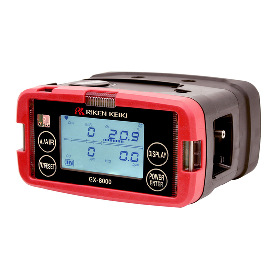
NOTE There are the following two combinations of battery units. The following information is printed on the battery unit for the sake of identification to prevent a mistake in combinations. BUL-8000 (certification number TC19437)=> BUL-8000(G) for Li-ion battery unit ... - Page 11 LCD display Displays gas concentrations, alarms, etc. Buzzer sound opening Emits a buzzer sound at an alarm. (Do not block it.) Alarm LED arrays The lamp blinks in response to an alarm. Infrared communication port Used to carry out data communications with a PC in data logger mode.
-
Page 12: Lcd Display
<LCD Display> (5) Pump driving (1) Pilot indicator indicator (2) Combustible gas (6) Oxygen concentration digital concentration digital and bar display and bar display (3) Carbon monoxide (7) Hydrogen sulfide concentration digital concentration digital and bar display and bar display (4) Battery level icon (8) Clock display Pilot indicator... -
Page 13: How To Use
How to Use 4-1. Before Using the Gas Monitor Not only the first-time users but also the users who have already used the product must follow the operating precautions. Ignoring the precautions may damage the gas monitor, resulting in inaccurate gas detection. 4-2. - Page 14 (1) Open the recharging jack cover of the gas monitor. CAUTION Do not pull the recharging jack cover too hard. It may get damaged. (2) Put the plug of the AC powered charger into the recharging jack of the gas monitor. (3) Connect the AC powered charger to the wall electric outlet.
- Page 15 <Replacing the Batteries in a Dry Battery Unit> When the gas monitor is used for the first time, or when the battery level is low, attach new AA alkaline batteries. CAUTION <Replacement> Turn off the power of the gas monitor before replacing the batteries. ...
- Page 16 <Detaching Battery Unit> (1) Loosen the two battery unit screws. (They need not be completely detached.) (2) Detach the battery unit. (3) Attach a new battery unit. NOTE Make sure that the battery unit is installed in correct orientation by checking the locations of the connection terminal and projection portions.
- Page 17 <Connection of Gas Sampling Probe and Gas Sampling Hose> Attach the gas sampling probe to the end of the gas sampling hose. Connect the sampling hose securely to the gas inlet (GAS IN) of the gas monitor. Insert the sampling hose to the gas inlet (GAS IN) until it clicks into place to ensure connection.
-
Page 18: Basic Operating Procedures
4-3. Basic Operating Procedures Normally, the detection mode is used for normal operations. (The detection mode is activated after the power is turned on.) <<Detection Mode>> RESET AIR (long pressing) <<Gas Alarm Status>> (Self-latching <Reset after <<Air Calibration Mode>> Recovery to Normal Status>) DISPLAY <<Fault Alarm Status>>... -
Page 19: How To Start The Gas Monitor
4-4. How to Start the Gas Monitor <<Start-up Procedure>> Keep the POWER switch pressed for three seconds or more. ↓ Alarm lamp lights up. All LCDs light up. Buzzer sounds once. (Beep) ↓ Date/Time Display ↓ Battery Voltage Display ↓ Gas Name Display ↓... - Page 20 ↓ STEL Alarm Setpoint Display ↓ TWA Alarm Setpoint Display ↓ ID Display ↓ Buzzer sounds twice. (Beep, beep) Detection Mode CAUTION After start-up, perform air calibration (air calibration mode) before performing gas detection. NOTE A sensor abnormality alarm is issued before the detection mode is entered if there is any abnormality in the sensor.
-
Page 21: How To Detect
4-5. How to Detect In the detection mode, put the gas sampling probe close to the detection area and take the reading on the display. Display example <- Display example CH4 concentration: 0%LEL O2 concentration: 20.9% CO concentration: 0 ppm H2S concentration: 0 ppm Time: 9:30... - Page 22 CAUTION Before performing gas detection, attach the gas sampling probe provided with the gas monitor to prevent disturbances by air dust. When you measure concentrations of oxygen in inert gases for a long time, the carbon dioxide concentration in the air must be 15% or less. When you use the gas monitor in the air with a carbon dioxide concentration of 15% or higher, perform measurement in as short time as possible.
- Page 23 <Manual Memory> Any instantaneous value during measurement can be recorded. Up to 256 points of data can be recorded. When the number of recorded data points reaches the maximum, recorded data will be overwritten, starting from the oldest data. (1) In the detection mode, keep the ▼/RESET switch pressed and press the ▲/AIR switch to prepare for recording (about one second).
- Page 24 <Auto Range Switching Point> (TYPE-A and E Only) If Auto Range is set on a type with the vol% range for combustible gases, the display is automatically switched to the vol% range when the concentration of a detected combustible gas exceeds 100%LEL. When the concentration drops, the display returns to the %LEL range again.
-
Page 25: Modes
4-6. Modes Details on each mode are provided as follows. (* Operations are slightly different depending on the type.) Mode Item LCD display Details ― Detection Concentration display Normal state Mode ― Air Calibration AIR CAL Perform the zero adjustment. Mode Display and Combustible... -
Page 26: Air Calibration Mode
4-7. Air Calibration Mode Press the AIR switch. Keep pressing the AIR switch. The screen says Adj - HOLD AIR. When RELEASE is displayed, release the AIR switch. A 30-second countdown is started on the LCD. (countdown for TC sensor versions only) When the zero adjustment is successfully completed, END... - Page 27 NOTE Air calibration can be performed even when there is a gas alarm. If the air calibration fails, it displays "FAIL" - "AIR CAL" and which sensor has become faulty. Press the RESET button to reset the fault alarm (calibration failure).
-
Page 28: Display/Setting Mode
4-8. Display/Setting Mode This mode allows you to change various displays and settings. Every time the DISPLAY switch is pressed, various screens are displayed in turn. (* Operations are slightly different depending on the type.) Detection Mode Display and Setting Mode Combustible Gas Measurement Combustible Gas Measurement Range Setting... - Page 29 Pump ON/OFF Setting Pump ON/OFF Setting P31 ENTER Used to turn on/off the pump operations. ID Display/Selection ID Display/Selection P32 ENTER Display an ID if it has been registered in advance. Also used to select an ID. Log Data Display Log Data Display ...
- Page 30 <Combustible Gas Measurement Range Setting "HC RANGE"> (TC sensor versions only) The models that can display combustible gas levels in two ways, "%LEL range" and "vol% range," automatically switch between these two displays according to the gas concentration or oxygen concentration, from "%LEL range"...
- Page 31 CAUTION No gas alarm is triggered in the combustible gas vol% range-only setting. In the vol% range-only setting, the screen displays [No ALARM] because no alarm is triggered. Be careful because the %LEL range-only setting screen does not appear different from the auto range setting screen.
- Page 32 <Full Scale Display/Alarm Setpoint Display/Alarm Test "ALARM-P"> Display the full scale or alarm setpoint values and check the alarm operations for the settings displayed. (1) Press the DISPLAY switch and select the "full scale display/alarm setpoint display/alarm test" from the display/setting mode menu.
- Page 33 <Pump ON/OFF Setting "PUMP OFF"> Used to turn the pump on and off. CAUTION While the pump operation is set to OFF, no gas detection is performed because no gas is drawn. The gas monitor does not automatically return to the detection mode if the pump operation is set to OFF.
- Page 34 <ID Display/Selection "ID SELECT"> Display an ID if it has been registered in advance. Also used to select an ID. (1) Press the DISPLAY switch and select the ID display/selection from the display/setting mode menu. The following screens are displayed in turn on the gas monitor. (2) Press the ENTER switch to set or select an ID.
-
Page 35: How To Exit
<Log Data Display "REC.DATA"> Display concentration data recorded to the manual memory. (1) Press the DISPLAY switch and select the log data display from the display/setting mode menu. The following screens are displayed in turn on the gas monitor. (2) Press the ENTER switch to display the log data. NOTE If you do not want to display the log data, press the DISPLAY switch to return to the display/setting mode menu. -
Page 36: Operations And Functions
Operations and Functions 5-1. Gas Alarm Activation Gas alarm: Triggered when the concentration of detected gas reaches or exceeds the alarm setpoint value. <<Self-latching>> Alarm display: Notified by blinking of a gas concentration value display, sounding of the buzzer, and lighting of the lamp. - Page 37 <Display Operation> Gas Concentration Display In a gas alarm, the gas concentration display and the alarm type display blink. In case of over the detection range (Over Scale), "∩∩∩" is displayed on the LCD. Display example Alarm Lamp The alarm consists of two steps. Each of them is triggered when the respective alarm setpoint value is reached to or exceeded.
-
Page 38: Fault Alarm Activation
5-2. Fault Alarm Activation Fault alarm: Triggered when an abnormality is detected in the gas monitor. <<Self-latching>> Alarm display: Notified by display of error messages, sounding of the buzzer, and lighting of the lamp. Alarm types: Low flow rate, sensor abnormality, battery voltage low, system abnormality, and calibration failure Determine the causes and take appropriate actions. -
Page 39: Maintenance
Maintenance This is an important instrument for the purpose of safety. To maintain the performance of the gas monitor and improve the reliability of safety, perform a regular maintenance. 6-1. Maintenance Intervals and Items Daily maintenance: Perform maintenance before beginning to work. ... -
Page 40: How To Clean
6-2. How to Clean Clean the gas monitor if it becomes extremely dirty. The gas monitor must be turned off while cleaning it. Use a wash cloth to remove dust. Do not use water or organic solvent for cleaning because they may cause malfunctions. - Page 41 No activated carbon filter is used on a type that does not measure carbon monoxide. Keep this knob tightened at all times. Use only an activated carbon filter dedicated to the gas monitor (GX-8000). Using a similar product may have harmful effects on the gas detection performance.
- Page 42 <Replacement of Regular Replacement Parts> List of recommended regular replacement parts Item Maintenance Replacement Quantity Remarks intervals intervals (pieces per unit) Rubber seal 2 years 1 set Tube 6 months 3 - 8 years 1 set Pump unit (RP-11) 6 months 1 - 2 years ...
-
Page 43: Calibration Mode
Demand flow regulator Calibration tubing Stopwatch Connection Connect the equipment as shown below to perform a calibration. GAS IN Gas sampling probe Demand flow (with a tube) regulator screwed into gas GAS OUT sampling cylinder (Open) GX-8000 main unit - 41 -... -
Page 44: Calibration Procedure
WARNING About the calibration gas Calibration gas is a hazardous gas (toxic, oxygen deficient, etc.). Handle the gas and related jigs and tools with due care (e.g., the gas must not be inhaled). About the calibration location Perform the calibration where no silicon, organic solvent, spray can gases, etc. are used. ... - Page 45 CAUTION Only Type-A, E *1 Perform the calibration in the following order: "fresh air adjustment, span adjustment, zero adjustment for high-concentration combustible gases, and span adjustment for high-concentration combustible gases. The sensor for high-concentration combustible gases has different outputs depending on whether the base gas is air or N2.
-
Page 46: Fresh Air Adjustment (Air Cal)
7-2. Fresh Air Adjustment (AIR CAL) WARNING When the fresh air adjustment is performed in the atmosphere, check the atmosphere for freshness before beginning the adjustment. If other gases exist, the adjustment cannot be performed properly, thus leading to dangers when the gas leaks. NOTE If the existence of other gases in the atmosphere is suspected before performing the fresh air adjustment, use a zero air gas cylinder and a demand flow regulator to perform the fresh air adjustment. - Page 47 AIR CAL Press the ENTER switch. The current concentration readings of the gases are displayed. Press the AIR switch when they are stabilized. When the AIR switch is pressed, HOLD AIR is displayed. Keep pressing the switch until RELEASE is displayed. Release the AIR switch.
-
Page 48: Span Adjustment
7-3. Span Adjustment <Simultaneous Span Adjustment for All Channels (AUTO CAL)> AUTO CAL Press the ENTER switch. The span gas concentration is displayed. Use the or switch to select the standard 4 <Span Gas Concentration sensors or the high concentration combustible gas Setting>... - Page 49 <Span Adjustment for Each Channel (ONE CAL)> ONE CAL Press the ENTER switch. The span adjustment selection menu is displayed. Press the or switch to display a target gas for which the span adjustment should be performed. Every time the or switch is pressed, the target gas is changed (in the order of Combustible, O2, H2S, CO, and ESCAPE).
-
Page 50: High Concentration Combustible Gas Zero Adjustment (Vol Z. Cal)
7-4. High Concentration Combustible Gas Sensor Zero Adjustment (VOL Z. CAL) for Type A and E Only VOL Z.CAL Press the ENTER switch. The VOL Z.CAL display blinks. Until the combustible gas range switches to VOL%, the combustible gas concentration is displayed as ---. The current concentration readings of the combustible gas and oxygen are displayed (prompting for supply). -
Page 51: Storage And Disposal
Storage and Disposal 8-1. Procedures to Store the Gas Monitor or Leave It for a Long Time The gas monitor must be stored under the following environmental conditions. In a dark place under the normal temperature and humidity away from direct sunlight ... -
Page 52: Disposal Of Products
8-3. Disposal of Products WARNING Do not disassemble the electrochemical type sensor or galvanic cell type sensor because they contain electrolyte. Electrolyte may cause severe skin burns if it contacts skin, while it may cause blindness if it contacts eyes. If electrolyte is adhered on you clothes, that part on your clothes is discolored or its material is decomposed. -
Page 53: Troubleshooting
Troubleshooting The troubleshooting does not explain the causes of all the malfunctions which occur on the gas monitor. This simply helps to find the causes of malfunctions which frequently occur. If the gas monitor shows a symptom which is not explained in this manual, or still has malfunctions even though remedial actions are taken, please contact RKI. - Page 54 Symptoms Causes Actions A low flow rate Water or oil, etc. was Check the gas sampling hose for any damage or mark of alarm is displayed. drawn in. drawn water or oil, etc. FAIL LOW FLOW The gas sampling hose Check the gas sampling hose for connections, clogging, is clogged.
-
Page 55: Product Specifications
Product Specifications 10-1. List of Specifications GX-8000 Model Detection principle Galvanic cell (OS) New ceramic catalytic(NC)/ Electrochemical (ES) Electrochemical (ES) Thermal conductivity(TE) Detectable gas Oxygen Combustible gas Hydrogen sulfide Carbon monoxide (O2) (HC/CH4/H2) (H2S) (CO) Measuring range 0~25vol% 0~100%LEL/~100vol% 0~30ppm 0~150ppm <Service range>... - Page 56 <Combinations of Detected Gases by Type> TypeA Oxygen (O2) Combustible (HC and CH4) * Hydrogen sulfide (H2S) Carbon monoxide (CO) TypeB Oxygen (O2) Combustible (HC and CH4) Hydrogen sulfide (H2S) Carbon monoxide (CO) TypeC Oxygen (O2) Combustible (HC and CH4) Hydrogen sulfide (H2S) TypeD Oxygen (O2)
-
Page 57: List Of Accessories
10-2. List of Accessories Battery unit: Li-ion battery unit (BUL-8000(G)) Dry battery unit (BUD-8000(G)) Standard AC powered charger (for Li-ion battery unit versions only) accessories Shoulder strap Gas sampling hose (1 m spiral) Gas sampling probe ... -
Page 58: Definition Of Terms
Definition of Terms vol% Gas concentration indicated in the unit of one-hundredth of the volume Gas concentration indicated in the unit of one-millionth of the volume %LEL An abbreviation for "Lower Explosion Limit." LEL refers to the lowest concentration of a combustible gas in air capable of causing explosion when ignited.
Need help?
Do you have a question about the GX-8000 and is the answer not in the manual?
Questions and answers