Table of Contents
Advertisement
Quick Links
P32 Series Sensitive Differential Pressure Switch
Installation Guide
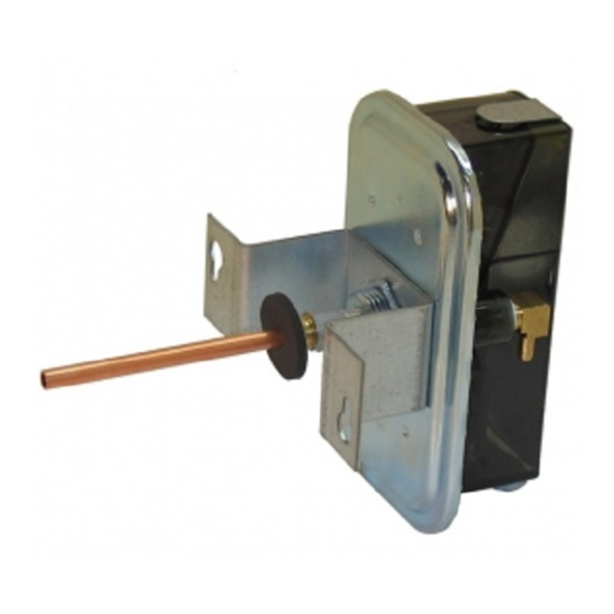
Figure 1: P32AC Differential Pressure Switch with
U mounting bracket and direct mounted sensing
probe assembled.
Application
This differential pressure switch is used to sense
the flow of air in ducts. When used with electric
strip heaters, the switch can be wired to open the
control circuit and de-energize the heaters when
air flow stops.
Important: P32 Series pressure switches are
intended to control equipment under normal
operating conditions. Where failure or malfunction
of a P32 pressure switch could lead to an abnormal
operating condition that could cause personal
injury or damage to the equipment or other
property, other devices (limit or safety controls) or
systems (alarm or supervisory) intended to warn
of or protect against failure or malfunction of the
P32 pressure switch must be incorporated into and
maintained as part of the control system.
Typical applications include:
•
Air flow proving with electric duct heaters
•
maximum air flow controller for variable air
Volume systems
•
Clogged filter detection
•
Detection of icing of air conditioning coils
and initiation of defrost cycle
For a P32 sensitive differential pressure switch
for combustion air applications, refer to P32
Series Sensitive Differential Pressure Switch For
Combustion Air Applications ( LIT-125430) at
https://docs.johnsoncontrols.com/bas/.
Operation
This differential pressure switch senses a change
in the differential pressure (either velocity pressure
or pressure drop across a fixed restriction in
the duct) as air flow in the duct changes. This
differential pressure, as sensed by the two sensing
ports, is applied to the two sides of a diaphragm in
the pressure switch.
The spring-loaded diaphragm moves and actuates
the switch when the air pressure difference
reaches the setpoint.
This switch can also be used to detect small
positive gauge pressure by using only the high
pressure connection and leaving the low pressure
connector open, or to detect a vacuum by using
only the low pressure connection and leaving the
high pressure connector open to ambient pressure.
Installation
Follow equipment manufacturer's instructions.
Locating
Select a location on or near the duct where
vibrations are minimal and the terminal screws
and adjusting screw are accessible. Ambient
temperature should be within the range of -40 to
167°F (-40 to 75°C) to avoid physical damage to
the control. The factory setting of the P32 is made
at room temperature. Ensure mounting locations
are as close to room temperature as possible.
Otherwise, for best performance, set switches
in the field in their mounted position and at the
normal ambient temperature for that application.
Mounting
The switch is normally mounted with the
diaphragm in a vertical position. It may be
fastened directly to the duct, heater, or panel as
long as the mounting surface has minimal or no
vibration.
Note: The switch is factory set with the
diaphragm in a vertical position. If it is mounted
in a horizontal position with the steel housing
(high pressure connector) down, the setpoint
will increase by about 0.07 in W.C. (.017 kPa). If
mounted with the steel housing up, the switch
may be inoperative at minimum setting. Adjustable
models can be readjusted for this mounting
position and minimum setpoint as follows:
1.
Mount the switch securely.
2.
Make sure no pressure is applied to either
connector.
3.
Turn the adjusting screw clockwise until the
switch operates and at least an additional 1/3
turn.
Important: When turning the fitting into the
plastic low pressure port, do not overtighten
and crack the threaded boss. Turn fitting in
finger-tight, then an additional 1 to 1 1/2 turns
(approximately 15 to 20 in.lb). Sealing compound
or tape is not required for the plastic low pressure
port.
Figure 2: Interior view of the P32AA Differential
Pressure Switch.
Part No. 996-100, Rev. F
Issue Date: May 2022
Figure 3: Direct mounting a P32 using the L
bracket as a mounting flange
Figure 4: Typical installation for a P32 Switch on
duct using Part No. BKT229-1R bracket and direct
mounting probe
Mounting for direct duct or heater
1.
Cut or drill a 7/8 in. (22 mm) diameter hole.
2.
Install tubing in the 1/8 in. NPT high pressure
(metal) connector, if required.
3.
Place the metal connector in the hole.
4.
Use a 1/2 in. conduit lock nut on the
connector and secure in place.
Advertisement
Table of Contents

Related Manuals for Penn P32 Series


Summary of Contents for Penn P32 Series
- Page 1 P32 Series Sensitive Differential Pressure Switch Part No. 996-100, Rev. F Installation Guide Issue Date: May 2022 for combustion air applications, refer to P32 Note: The switch is factory set with the Series Sensitive Differential Pressure Switch For diaphragm in a vertical position. If it is mounted...
- Page 2 CHINA www.penncontrols.com ® Johnson Controls and Penn are registered trademarks of Johnson Controls in the United States of America and/or other countries. All other trademarks used herein are the property of their respective owners. © Copyright 2022 by Johnson Controls.
Need help?
Do you have a question about the P32 Series and is the answer not in the manual?
Questions and answers