Advertisement
Installation
Important: Use this F61 Series Standard Flow Switch only to control equipment under
normal operating conditions. Where failure or malfunction of the flow switch could lead to
personal injury or property damage to the controlled equipment or other property, additional
precautions must be designed into the control system. Incorporate and maintain other
devices, such as supervisory or alarm systems or safety or limit controls, intended to warn of
or protect against failure or malfunction of the flow switch.
Important : Utiliser ce F61 Series Standard Flow Switch uniquement pour commander des
équipements dans des conditions normales de fonctionnement. Lorsqu'une défaillance ou
un dysfonctionnement du flow switch risque de provoquer des blessures ou d'endommager
l'équipement contrôlé ou un autre équipement, la conception du système de contrôle doit
intégrer des dispositifs de protection supplémentaires. Veiller dans ce cas à intégrer de façon
permanente d'autres dispositifs, tels que des systèmes de supervision ou d'alarme, ou des
dispositifs de sécurité ou de limitation, ayant une fonction d'avertissement ou de protection en
cas de défaillance ou de dysfonctionnement du flow switch.
Some models of the F61 Series Standard Flow Switches require installation or adjustment of
paddles prior to mounting. See
Parts Included
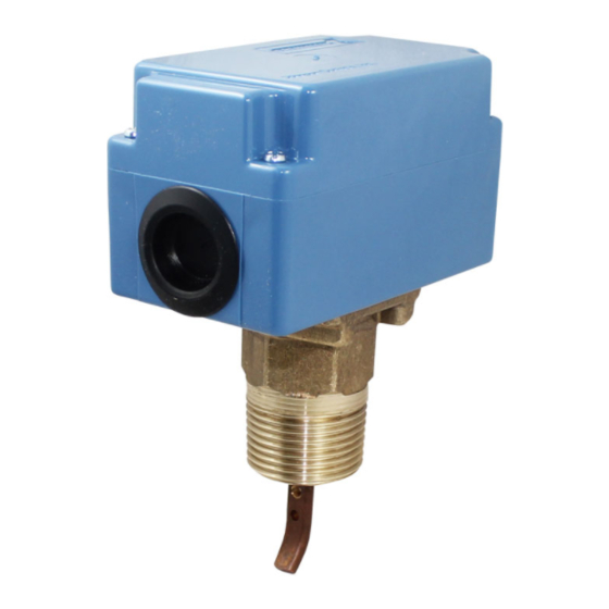
Standard models of the F61 flow switch include an installed three-piece flow paddle. Some models
also include a large flow paddle for large pipe sizes.
Table 1: Replacement Parts
Kit Number
KIT21A-600
KIT21A-601
PLT52A-600R
CVR62A-600R
Installing the Flow Paddles
Important: To allow the switch to detect changes in the fluid flow, the flow paddle must not
touch the pipe or any restrictions in the pipe.
Adjust flow paddles to the size of the pipe used. If needed, trim the large flow paddle at the arc
corresponding to pipe size (see Figure 1 and Figure 2) and install.
Part No. 24-8407-4 Rev. D
2019-04-04
F61 Series Standard Flow Switches
Installing the Flow
Paddles.
Description
Stainless Steel Three-piece Paddle (3 in., 2 in., and 1 in. Segments)
Stainless Steel 6 in. Paddle
Stainless Steel Three-piece Paddle (3 in., 2 in., and 1 in. Segments) and
6 in. Paddle
Replacement Cover Assembly for LB, MB, MD, and MG types
Installation Guide
F61KB, F61LB, F61MB, F61MG
Advertisement
Table of Contents

Subscribe to Our Youtube Channel
Summary of Contents for Penn F61 Series
- Page 1 Some models of the F61 Series Standard Flow Switches require installation or adjustment of paddles prior to mounting. See Installing the Flow Paddles.
- Page 2 Figure 1: Installing the Paddles Figure 2: Trimming Diagram for Large Flow Paddle Dimensions Figure 3: NEMA 1 Enclosure (F61KB Types) Dimensions, in. (mm) F61 Series Standard Flow Switches Installation Guide...
- Page 3 Important: To avoid damaging the switch, do not tighten the switch to the tee by grasping the switch enclosure. Use only the wrench flats provided. Mount the F61 Series Flow Switch, using the following guidelines: • Install the switch so that the cover and interior are accessible.
- Page 4 • Install all wiring in accordance with the National Electrical Code and local regulations. Make all wiring connections using copper conductors only. Do not exceed the control’s electrical rating. F61 Series Standard Flow Switches Installation Guide...
-
Page 5: Setup And Adjustments
• Sealed settings (screws marked with black paint) are not intended to be changed. Adjustment attempts may damage the control or cause loss of calibration, voiding the warranty. To adjust the setting of the flow switch: F61 Series Standard Flow Switches Installation Guide... - Page 6 (0.95) (1.32) (1.70) (3.11) (4.09) (6.24) (14.8) (28.4) (43.2) (85.2) Flow Decrease (R to B 2.50 3.70 5.00 9.50 12.5 19.0 50.0 Closes) (0.57) (0.84) (1.14) (2.16) (2.84) (4.32) (11.4) (22.9) (35.9) (72.7) F61 Series Standard Flow Switches Installation Guide...
- Page 7 Adjustment Flow Decrease (R to B Closes) 76.0 (17.3) 111 (25.2) 135 (30.7) 400 (90.8) Where paddle size is larger than pipe size, values are for 6 in. paddle trimmed to fit pipe. F61 Series Standard Flow Switches Installation Guide...
-
Page 8: Troubleshooting
Repairs and Replacement Do not make field repairs, except for replacement of the cover and paddles. For a replacement flow switch, paddle kit or cover, contact the nearest Johnson Controls/ PENN™ distributor. For more information, contact Refrigeration Application Engineering at (800) 275-5676. - Page 9 Johnson Controls office. Johnson Controls shall not be liable for damages resulting from misapplication or misuse of its products Refer to the F61 Series Flow Switches Product/Technical Bulletin (LIT-125225) for necessary information on operating and performance specifications of this product.
- Page 10 © 2019 Johnson Controls. All rights reserved. All specifications and other information shown were current as of document revision and are subject to change without notice. www.penncontrols.com...


Need help?
Do you have a question about the F61 Series and is the answer not in the manual?
Questions and answers