Table of Contents
Advertisement
Quick Links
Applications
Important:
• Do not install or use this F261 Series Flow Switch in
or near environments where corrosive substances
or vapors could be present. Exposure of the F261
Series Flow Switch to corrosive environments may
damage the device's internal components and will
void the warranty.
• Do not use F261 Series Flow Switches where the
fluid in the pipes drops below the fluid's freezing
point, causing an internal freeze-up.
Important: Use this F261 Series Flow Switch only as
an operating control. Where failure or malfunction
of the flow switch could lead to personal injury or
property damage to the controlled equipment or
other property, additional precautions must be
designed into the control system. Incorporate and
maintain other devices, such as supervisory or alarm
systems or safety or limit controls, intended to warn
of or protect against failure or malfunction of the
flow switch.
Important: Utiliser ce F261 Series Flow Switch
uniquement en tant que dispositif de régulation.
Lorsqu'une défaillance ou un dysfonctionnement
du flow switch risque de provoquer des blessures
ou d'endommager l'équipement contrôlé ou un
autre équipement, la conception du système de
contrôle doit intégrer des dispositifs de protection
supplémentaires. Veiller dans ce cas à intégrer de
façon permanente d'autres dispositifs, tels que
des systèmes de supervision ou d'alarme, ou des
dispositifs de sécurité ou de limitation, ayant une
fonction d'avertissement ou de protection en cas de
défaillance ou de dysfonctionnement du flow switch.
F261 Series Flow Switches Installation Guide
Risk
This product is made of a copper alloy, which contains
lead. The product is therefore not to be used on
drinking water.
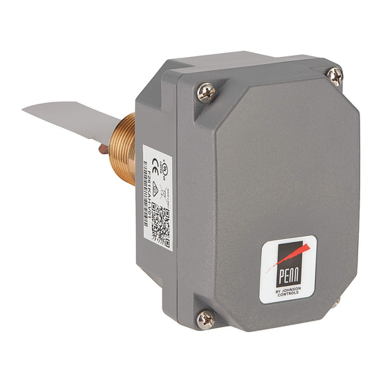
The F261 Series Flow Switches respond to fluid flow in lines
carrying water, ethylene glycol, or other nonhazardous
fluids. These models also work in applications with
swimming pool water and lubricating oils.
F261 Series Standard Flow Switches use a variety of
paddle sizes to respond to fluid flow rates in applications
with 1 inch trade size (or greater) pipe.
F261 Series Low Flow Switches respond to low fluid flow
rates in applications with 1 inch trade size (or less) pipe.
A low-energy model with gold-plated contacts provides
improved electrical performance in low-voltage, low-
current circuits to operate small relays, solenoid valves,
and electronic control circuits.
Installation
F261 Series Standard Flow Switches come with 1 in., 2 in.,
3 in., and 6 in. stainless steel flow paddles, a paddle screw
and a lock washer. For replacement parts, see Table 2.
Part No. 24-7664-2969 Rev. F
WARNING
F261KEH, F261MEH, F261KFH, F261MFH
2020-11-19
Advertisement
Table of Contents

Subscribe to Our Youtube Channel
Related Manuals for Penn F261 Series


Summary of Contents for Penn F261 Series
- Page 1 2020-11-19 Applications WARNING Important: • Do not install or use this F261 Series Flow Switch in or near environments where corrosive substances Risk or vapors could be present. Exposure of the F261 This product is made of a copper alloy, which contains Series Flow Switch to corrosive environments may lead.
- Page 2 Dimensions Figure 1: F261 standard flow switch dimensions, in. (mm) Figure 2: F261 low-flow switch dimensions, in. (mm) F261 Series Flow Switches Installation Guide...
- Page 3 Remove flow paddles that are too large to • 1 in. fit the pipe diameter. For flow paddle installation information, see 6 in. (162 mm) • 6 in. Figure 4. • 3 in. • 2 in. • 1 in. F261 Series Flow Switches Installation Guide...
- Page 4 • To avoid damaging the switch, do not tighten the switch to the tee by grasping the switch enclosure. To mount the F261 Series Flow Switches, observe the following guidelines: For standard 1 in. x 1 in. pipe installation, mount the F261 •...
- Page 5 60 degrees of vertical. See components are at AC line voltage. Contact with Figure 9. components carrying hazardous voltage can cause electric shock and may result in personal injury or death. F261 Series Flow Switches Installation Guide...
-
Page 6: Setup And Adjustments
Increase Red to yellow d'autres dégâts matériels. Decrease Red to blue To adjust the setting of the flow switch: Disconnect the power supply before making any electrical connections. Remove the enclosure cover. F261 Series Flow Switches Installation Guide... - Page 7 (53.4) (81.8) (166) Values for 2 in. paddle trimmed to pipe. Values for a 3 in. paddle trimmed to fit pipe. Values calculated for a factory-installed set of 1, 2, and 3 in. paddles. F261 Series Flow Switches Installation Guide...
- Page 8 76.0 (1.93) 111 (25.2) 135 (30.7) 400 (90.8) (Close R to B) Table 9: GPM (L/Min) required to actuate F261 Series Low Flow Switches Pipe size 1/2 x 1/2 in. female 3/4 x 3/4 in. female 3/4 x 3/4 in. female...
-
Page 9: Operation
Maximum dry circuit rating: Resistive only, 400 mW at 28 VAC/VDC. After you use a relay at the general rating level, The control switch Ensure that the connections the dry circuit rating is no longer valid. action is reversed. follow the wiring diagrams. F261 Series Flow Switches Installation Guide... -
Page 10: North American Emissions Compliance
F261 Series flow switches technical Table 16: F261 Series fluid flow switches technical specifications specifications Specification Description Table 15: UL conformity declaration information Pipe connector Standard: 1 in. 11-1/2 NPT Threads Information Description Low-Flow: 1/2 in. x 1/2 in. Female NPTF;... -
Page 11: Product Warranty
507 E MICHIGAN ST MANAGEMENT 45143 ESSEN MILWAUKEE WI 53202 NO. 32 CHANGJIJANG RD NEW GERMANY DISTRICT WUXI JIANGSU PROVINCE 214028 CHINA Contact information Contact your local branch office: www.johnsoncontrols.com/locations Contact Johnson Controls: www.johnsoncontrols.com/ contact-us F261 Series Flow Switches Installation Guide... - Page 12 © 2020 Johnson Controls. All rights reserved. All specifications and other information shown were current as of document revision and are subject to change without notice. www.penncontrols.com...
Need help?
Do you have a question about the F261 Series and is the answer not in the manual?
Questions and answers