Table of Contents
Advertisement
Quick Links
Applications
Important: Use this F262 Series Airflow Switch only
as an operating control. Where failure or malfunction
of the F262 switch could lead to personal injury
or property damage to the controlled equipment
or other property, additional precautions must be
designed into the control system. Incorporate and
maintain other devices, such as supervisory or alarm
systems or safety or limit controls, intended to warn
of or protect against failure or malfunction of the
F262 switch.
Important: Utiliser ce F262 Series Airflow Switch
uniquement en tant que dispositif de régulation.
Lorsqu'une défaillance ou un dysfonctionnement
du F262 switch risque de provoquer des blessures
ou d'endommager l'équipement contrôlé ou un
autre équipement, la conception du système de
contrôle doit intégrer des dispositifs de protection
supplémentaires. Veiller dans ce cas à intégrer de
façon permanente d'autres dispositifs, tels que
des systèmes de supervision ou d'alarme, ou des
dispositifs de sécurité ou de limitation, ayant une
fonction d'avertissement ou de protection en cas de
défaillance ou de dysfonctionnement du F262 switch.
The F262 Series Airflow Switch detects airflow or the
absence of airflow only in response to the velocity of air
movement within a duct. You can wire the switch to open
one circuit and close a second circuit, single-pole, double-
throw (SPDT), for either signaling or interlock purposes.
Airflow failure during the normal operation of air handling
systems may cause overheating, coil icing, or other
conditions that may be detrimental to the equipment.
Typical applications include:
• Make-up air systems
• Air cooling or heating processes
• Exhaust systems
F262 Series Airflow Switch Installation Guide
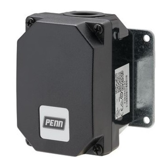
The switch has a Type 3R/IP43 enclosure with an integral
Mounting plate. A mounting plate gasket is supplied with
each control.
The enclosed SPDT Penn switch has color-coded
terminals for ease of wiring. The control is factory set
at approximately the minimum flow rate. See Table 1.
You must not set the control any lower than the factory
setting because the control may fail to return to a no-flow
condition. If you require a higher flow rate setting, turn
the range adjusting screw clockwise.
Mount the F262 switch on the top, side, or bottom of a
duct in a horizontal position whenever possible. If vertical
duct mounting is required and the flow is downward, you
must readjust the control. If the flow is upward, refer to
Table 1 for minimum flow required to actuate the control.
The switch is not designed for use where it is exposed to
outside weather.
Part No. 24-7664-2977 Rev. E
2021-04-20
F262AA
Advertisement
Table of Contents

Related Manuals for Penn F262 Series


Summary of Contents for Penn F262 Series
- Page 1 F262 switch. The F262 Series Airflow Switch detects airflow or the absence of airflow only in response to the velocity of air movement within a duct. You can wire the switch to open one circuit and close a second circuit, single-pole, double- throw (SPDT), for either signaling or interlock purposes.
- Page 2 - The standard paddle fits into ducts of 3 in. × 8 in. (76 mm × 203 mm) minimum. - You can trim the paddle for installation in ducts as small as 3 in. × 6 in. (76 mm × 152 mm). F262 Series Airflow Switch Installation Guide...
- Page 3 Table 1 for the minimum flow required to actuate the switch. The maximum air velocity must not exceed 2,000 fpm (10.16 m/s). Figure 5: Mounting the F262 control in a vertical duct F262 Series Airflow Switch Installation Guide...
- Page 4 Toute tentative de réglage risque is present within the duct. d'endommager le dispositif de contrôle ou de provoquer la perte des valeurs d'étalonnage ou d'autres dégâts matériels. F262 Series Airflow Switch Installation Guide...
- Page 5 Johnson Controls /Penn distributor. ® F262 Airflow Switch technical specifications Table 3: F262 Series Airflow Switch electrical ratings Volts 50/60 Hz UL 60730/UL 1059 EN 60730 Note: Do not lower the flow rate required to activate the switch unless it is set above the Horsepower –...
- Page 6 Wire/cord temperature ratings: conditions beyond these specifications, consult Johnson rating • 140°F (60°C) only permitted when Controls or PENN Refrigeration Application Engineering at ambient air and media are less than 1-800-275-5676. Johnson Controls shall not be liable for 113°F (45°C) damages resulting from misapplication or misuse of its •...
- Page 7 507 E MICHIGAN ST MANAGEMENT 45143 ESSEN MILWAUKEE WI 53202 NO. 32 CHANGJIJANG RD NEW GERMANY DISTRICT WUXI JIANGSU PROVINCE 214028 CHINA Contact information Contact your local branch office: www.johnsoncontrols.com/locations Contact Johnson Controls: www.johnsoncontrols.com/ contact-us F262 Series Airflow Switch Installation Guide...
- Page 8 © 2021 Johnson Controls. All rights reserved. All specifications and other information shown were current as of document revision and are subject to change without notice. www.penncontrols.com...
Need help?
Do you have a question about the F262 Series and is the answer not in the manual?
Questions and answers