Table of Contents
Advertisement
Quick Links
Advertisement
Table of Contents

Related Manuals for Inter-m MEQ-2000

Summary of Contents for Inter-m MEQ-2000
- Page 1 MEQ-2000 24/96 Multimode Equalizer Copyright 2004 Inter-M Corporation...
-
Page 2: Table Of Contents
Welcome ... 5 Unpacking ...6 Warnings ...6 Operation ...7 Features ... 8 OVERVIEW – Front Panel Controls ... 9 OVERVIEW – Rear Panel Controls... 11 OVERVIEW – Signal Flow Diagram ... 12 OVERVIEW – Operating Modes... 13 SETUP MENU – Device Status ... 14 Setup Menu Structure ...15 SETUP MENU –... - Page 3 MEQ-2000 24/96 Multimode Equalizer UTILITY MENU STRUCTURE... 49 MEMORY MENU ... 50 Technical Specifications ... 53 Block Diagram ... 56 APPENDIX I – SYSEX (System-Exclusive) Message Definitions... 57 Appendix II - Jumpers... 77...
- Page 4 MEQ-2000 24/96 Multimode Equalizer...
-
Page 5: Welcome
A personal welcome to you from the management and employees of Inter-M All of us here at Inter-M are dedicated to providing you with the highest quality products and the best value. We sincerely trust this product will provide you with years of satisfactory service. If anything is not to your complete satisfaction, we will endeavor to make things right. -
Page 6: Unpacking
MEQ-2000 24/96 Multimode Equalizer Unpacking Your MEQ-2000 is a feature-rich, professional device. We strongly recommend you take the time to read this comprehensive manual and familiarize yourself with the important information regarding product features, setup and operation. As with most electronic devices, we strongly recommend you retain the original packaging. -
Page 7: Operation
MEQ-2000 24/96 Multimode Equalizer 12. Use only with a cart, stand, tripod, bracket, or table specified, or sold with the apparatus. When a cart is used, use caution when moving the cart/apparatus combination to avoid overturning. 13. Unplug this apparatus during lightning storms or when it will be unused for a long period of time. -
Page 8: Features
MEQ-2000 24/96 Multimode Equalizer Features • Traditional warm analog sound coupled with state-of-the-art digital signal processing. • Digital I/O on AES/EBU or S/PDIF with comprehensive Sample Rate Conversion: Input rates of 20-100kHz, Output rates of 32, 44.1, 48, 64, 88.2 and 96 kHz. -
Page 9: Overview - Front Panel Controls
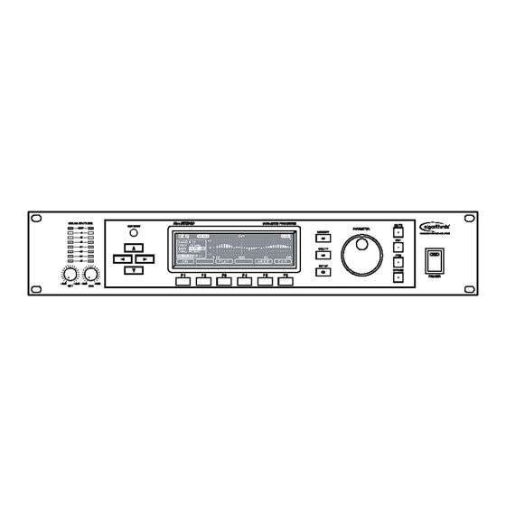
OVERVIEW – Front Panel Controls 1. Input Levels Two analog input level controls with ±12dB range. 2. Input Level Meters Two eight-segment LED level meters with Clip indicators. 3. LCD Display Blue backlit LCD 240 X 64 display provides instant parameter readouts. 4. - Page 10 9. Power Switch This switch is used to switch the unit on and off. When the unit is on, the integrated Power Indicator LED is lit. 10. LCD Contrast Adjustment This knob adjusts the contrast of the LCD display, for better readability at different angles and in varied lighting.
-
Page 11: Overview - Rear Panel Controls
OVERVIEW – Rear Panel Controls 1. Analog Inputs Analog audio inputs on balanced three-pin female XLR connectors. 2. Analog Outputs Analog audio outputs on balanced three-pin male XLR connectors. 3. Digital Inputs Digital audio inputs: AES/EBU on XLR connector, S/PDIF coaxial on RCA connector, and S/PDIF optical on TOSLINK connector. -
Page 12: Overview - Signal Flow Diagram
MEQ-2000 24/96 Multimode Equalizer OVERVIEW – Signal Flow Diagram... -
Page 13: Overview - Operating Modes
OVERVIEW – Operating Modes The MEQ-2000 can function as a valuable tool for a number of different applications, including: • Recording • Mixing • Mastering • Sound Reinforcement • Acoustical Measurements The MEQ-2000’s internal algorithms consist of a number of complex modules, capable of multiple operations. -
Page 14: Setup Menu - Device Status
SETUP MENU – Device Status Pressing the Setup Button to the right of the LCD display opens the DEVICE STATUS menu, displaying the unit’s configuration, audio inputs and outputs. The screen reads DEVICE STATUS, and the soft keys display the setup menu options. The DEVICE STATUS screen displays a number of important function parameters: INPUT Displays the current input, as selected in the CONFIG menu. -
Page 15: Setup Menu Structure
FS INTERNAL Indicates the internal sampling frequency. This should always read 96kHz. FSI MEASURED Displays the actual sampling frequency of the signal at the selected digital input. Setup Menu Structure... -
Page 16: Setup Menu - Setup Screen
SETUP MENU – Setup Screen The Setup Screen performs a number of functions, depending on which modules are selected. When the Setup Screen is first called up, the Status Screen displays the unit’s hardware setup (see previous section). The Soft Keys at the bottom of the screen bring up the unit’s various processing functions. -
Page 17: Parameter Wheel
Every processing function selected by the Soft Keys brings up an application-specific menu, assigning new labels to the Soft Keys. The illustration below shows the Graphic Equalizer (GEQ) screen: The PARAMETER WINDOW on the left side of the display shows the current module’s parameters. -
Page 18: Setup Menu - Parametric Equalizer (Peq)
SETUP MENU – Parametric Equalizer (PEQ) The Parametric Equalizer (PEQ) offers eight high-precision digital filters: six constant-Q bell filters, a low shelving and high shelving filter. A Master Gain parameter is provided to compensate for gain changes after equalization. There are five active buttons in PEQ mode: F1 –... -
Page 19: Peq Mode Screen
appears instead of BW or Q when LS or HS (shelving) is chosen in the FILT menu. It selects the shelving slope of 3, 6, or 9dB per octave. PEQ MODE Screen By pressing the MODE button you can access the PEQ MODE screen, which allows for global setup changes in the PEQ module. -
Page 20: Setup Menu - Graphic Equalizer (Geq)
SETUP MENU – Graphic Equalizer (GEQ) The Graphic Equalizer (GEQ) offers 31 bands of 1/3-octave equalization over a frequency range of 20Hz to 20kHz. There are five active buttons in GEQ mode: F1 – ON Switches the GEQ module on or off. F2 –... -
Page 21: Geq Mode Screen
GEQ MODE Screen By pressing the MODE button you can access the GEQ MODE screen, which allows for global setup changes in the GEQ module. In this screen, parameters are selected with the with the parameter wheel. After every change, ENTER appears at the F5 key, and must be pressed to confirm the change. -
Page 22: Setup Menu - Notch And Cut Filters (Cut)
SETUP MENU – Notch and Cut Filters (CUT) Notch and High/Low Cut filter module (CUT) offers effective feedback or hum suppression through six very narrow, adjustable notch filters. There are six active buttons in CUT mode: F1 – ON Switches the CUT module on or off. F2 –... -
Page 23: Cut Mode Screen
GAIN selects boost or cut value (Notch filter only) over a range of 0 to –24dB in 1dB increments. For manual feedback search, notch filters can also be adjusted to a positive gain of up to +8dB. BW or Q selects the filter bandwidth of the active Notch filter. -
Page 24: Setup Menu - Delay
SETUP MENU – Delay The DELAY module provides delays for different loudspeakers or microphone positions, for use in large-scale sound reinforcement. There are six active buttons in DELAY mode: F1 – ON Switches the DELAY module on or off. F2 – LINK Couples CH1 and CH2. -
Page 25: Delay Mode Screen
sets the DELAY length over a range of 0 – 1240 ms, in 1 ms (Coarse) or 0.01 ms (Fine) steps. DIST sets the distance in meters over a range of 0 to 430 meters. Delay time in LEN is computed using DIST and TEMP settings. TEMP selects the environment temperature over a range of 0 to 50 degrees Celsius, in 0.5 degree increments, or from 32 to 121 degrees Fahrenheit, in... -
Page 26: Setup Menu - Compressor/Limiter (Com/Lim)
SETUP MENU – Compressor/Limiter (COM/LIM) The COM/LIM module is a combination of compressor and limiter algorithms, designed primarily for mastering type compression. It provides a useful mix of compression and limiting functions, depending on the task you need to address. For example, it can provide a smoother compression ratio for a vocal or instrumental track, or a hard limiter for avoiding peaks in a mixdown. - Page 27 The screen below displays the second set of parameters available: adjusts the attack time over a range of 0.1 ms to 20 ms in 0.1 ms increments. adjusts the release time over a range of 10ms to 5000 ms in 10 ms increments.
-
Page 28: Com/Lim Mode Screen
COM/LIM MODE Screen Pressing the MODE key accesses the COM/LIM MODE screen, which allows for global setups for the COM/LIM module. In this screen, parameters are selected with the with the parameter wheel. After every change, ENTER appears at the F5 key, and must be pressed to confirm the change. -
Page 29: Setup Menu - Limiter
SETUP MENU – Limiter The LIMITER module is a true peak limiter, typically used as a final stage in sound reinforcement. It is useful for achieving maximum gain without overloading. There are four active buttons in LIMITER mode: F1 – ON Switches the LIMITER module on or off. -
Page 30: Limiter Mode Screen
LIMITER MODE Screen Pressing the MODE key accesses the LIMITER MODE screen, which allows for global setups for the LIMITER module. In this screen, parameters are selected with the with the parameter wheel. After every change, ENTER appears at the F5 key, and must be pressed to confirm the change. -
Page 31: Setup Menu - Real Time Analyzer (Rta)
SETUP MENU – Real Time Analyzer (RTA) The Real Time Analyzer (RTA) displays the spectral content of an input or output signal. It is based on a 31-band filter, utilizing 1.3-octave ISO specification over a spectrum of 20Hz to 20kHz. An RTA-Hold function is provided to sample the analyzed signal; this envelope can be used as a weighting reference for the GEQ module. -
Page 32: Rta Mode Screen
Pressing the F6 (EXIT) key returns to the RTA screen. If the MEQ-2000 is in measurement mode (ME-1 or ME-2), GREF (GEQ Reference) appears over the F3 soft key. Pressing this key stores the current spectral envelope as a weighting reference for the GEQ module in RE-1, RE-2, MA-1 and MA-2 modes. -
Page 33: Setup Menu - Level Adjustment (Levels)
SETUP MENU – Level Adjustment (LEVELS) The LEVELS module provides adjustment of the digital gains of the input and output paths of the system. There are five active buttons in LEVELS mode: F1 – ON Switches the LEVELS on or off. In the On position the system gains are optimally adjusted to unity gain. -
Page 34: Levels Mode Screen
LEVELS MODE Screen Pressing the MODE key accesses the LEVELS MODE screen, which allows for global setups for the LEVELS module. In this screen, parameters are selected with the parameter wheel. After every change, ENTER appears at the F5 key, and must be pressed to confirm the change. -
Page 35: Setup Menu - Reference Generator (Gen)
SETUP MENU – Reference Generator (GEN) The Reference Generator (GEN) is a precision tool providing high-quality audio test signals. The THD+N of the generated sine wave is better than –144dB. For acoustical measurements, uncorrelated white and pink noise generators are available. The signal frequency’s range extends to subsonic and ultrasonic ranges, from 10Hz to 43.5kHz. -
Page 36: Levels Mode Screen
AMPL adjusts the signal amplitude over a range of –144 to 0dBFs, in increments of 0.1dB for 24-bit output; -120dBFs for 20-bit output; and –96dBFs for 16-bit output. FREQ adjusts the sine wave frequency over a range of 10Hz to 43.5kHz in 1/12 octave (COARSE) or 1Hz (FINE) increments. - Page 37 Global parameters available in the GEN MODE screen are primarily related to the sweep function: CH LINK determines the channel coupling status: OFF selects dual channel mode, with two independent channels. CH1→2 couples the channels with CH1 slaved to CH2. CH2→1 couples the channels with CH2 slaved to CH1.
-
Page 38: Utility Menu - Device Status
UTILITY MENU – Device Status Press the UTIL button to the right of the LCD display to open the Utility menu. The screen shows DEVICE STATUS and the soft keys offer the status mode’s options. Additional options can be accessed via the MORE key (included in the Appendix, beginning on page 56). There are six active buttons in UTIL mode: F1 –... -
Page 39: Utility Menu - System Configuration (Config)
UTILITY MENU – System Configuration (CONFIG) The configuration status of the MEQ-2000 processing modules may be optimized for various applications. Three main setup modes are provided: Mastering/Recording – with a mastering compressor/limiter used pre or post PEQ. Sound Reinforcement – with a peak limiter implemented at the end of the signal chain. -
Page 40: Parameter Window
After every change, ENTER appears at the F5 key, and must be pressed to confirm the change. Note that any configuration change causes the MEQ-2000 to reconfigure the module chain. Therefore after pressing ENTER to confirm a change, the system will mute all outputs for a few seconds while reconfiguring. - Page 41 After every change, ENTER appears at the F5 key, and must be pressed to confirm the change. Note that any configuration change causes the MEQ-2000 to reconfigure the module chain. Therefore after pressing ENTER to confirm a change, the system will mute all outputs for a few seconds while reconfiguring.
-
Page 42: Typical Digital Interconnections
MEQ-2000 24/96 Multimode Equalizer Typical Digital Interconnections... -
Page 43: Utility Menu - Remote Control
UTILITY MENU – Remote Control The MEQ-2000 can be remotely controlled by RS-232 or MIDI. Any programmable hardware of software MIDI controller may be used. A list of available commands is included in Appendix I. The Inter-M/Algorithmix proprietary remote software (DSP-2000R) provides excellent visual control of the MEQ-2000’s processing features, with fully bi-directional... -
Page 44: Utility Menu - Adc Calibration
MEQ-2000 24/96 Multimode Equalizer UTILITY MENU – ADC Calibration For critical applications, it is sometimes desirable to calibrate the analog-to-digital converters some 30 minutes after switching the unit on. While the ADC is calibrated automatically when the unit is switched on, minor drifts may occur in the input signal during warm-up. -
Page 45: Utility Menu - Device Security Lock
24/96 Multimode Equalizer UTILITY MENU – Device Security Lock To protect the MEQ-2000 from accidental or unauthorized changes, the device security lockout function is provided. There are two levels of security lock: a simple lock/unlock function, and a password protected lock/unlock function. -
Page 46: Utility Menu - Device Id Numbers
UTILITY MENU – Device ID Numbers Pressing the ID key in the UTILITY menu accesses the Device ID screen, which displays unique identifying information for your MEQ-2000. You will need these numbers before contacting technical support, or to download software updates or special software plug- ins. -
Page 47: Utility Menu - Auxiliary Functions
UTILITY MENU – Auxiliary Functions Pressing the AUX key in the UTILITY menu provides access to some global settings. Two parameters are available, and can be accessed with the BACKLIGHT provides for automatic shut-off of the LCD backlight after 1, 3 or 5 minutes. The backlight can be set to an always-on state as well (select ON), however selecting an auto-off setting will increase the life-span of the backlight. -
Page 48: Utility Menu - Software Update
Device ID screen (see page 45). To perform an update, connect the MEQ-2000’s RS-232 interface to a serial port on your computer. The MEQ-2000 should be placed in UPDATE mode before beginning the software download. -
Page 49: Utility Menu Structure
MEQ-2000 24/96 Multimode Equalizer UTILITY MENU STRUCTURE... -
Page 50: Memory Menu
MEMORY MENU Any selected parameters included in the SETUP menu may be stored as a user preset for later recall. In general, there are two types of presets: temporary and permanent. Temporary presets are accessed via the PR1 and PR2 keys, and are useful for quick comparisons of up to three setups (current, PR1 and PR2). - Page 51 After loading a factory or user preset, its number appears in the upper right of the display (e.g., F04 or U23). If any changes are made to the preset’s parameters, a appear in front of the preset number, to indicate that the preset has been modified. Using the cursor keys or the parameter wheel, you can select any memory position in the USER or FACT banks.
- Page 52 FACTORY bank, and store up to eight of your own USER settings. The MEQ-2000 also provides a number of Global Presets which include complete setup of the entire unit. They can be recalled by pressing the UTILITY and MEMORY keys. The unit ships with two factory presets installed: GENERAL DEFAULT and MEASUREMENT1.
-
Page 53: Technical Specifications
Technical Specifications Signal Processing Functions (per channel) ARAMETRIC QUALIZER Digital Filters Shelving Slope Extended Frequency Range Bandwidth Boost/Cut Range RAPHIC QUALIZER Filters Bandwidth Boost/Cut Range Filter Bank Type ILTER LOCK Low-Cut Frequency Range High-Cut Frequency Range Slope Characteristics Notch Filters Frequency Range Frequency Resolution Q (Bandwidth) - Page 54 ASTER ELAY Length Resolution Attenuation Phase Invert & Channel Sweep Dithering Levels 1/3 O CTAVE PECTRUM 31-Band conform to GEQ Peak-Hold Function with Reset Adjustable Averaging and Decay Time Adjustable Display Range: Maximal Level and Zoom Inverse Spectral Function as a reference for GEQ EFERENCE IGNAL ENERATOR...
- Page 55 Analog Outputs Impedance Maximum Signal Level Output Level Gain Digital Outputs Coaxial and Optical Sample Rate AUDIO PERFORMANCE A/D conversion D/A conversion Digital In/Out Internal Sampling Frequency Calculation Resolution Internal Signal Path Inherent System Delay Analog Input Frequency Range Dynamic Range Crosstalk Analog Output Frequency Range...
-
Page 56: Block Diagram
MEQ-2000 24/96 Multimode Equalizer Block Diagram... -
Page 57: Appendix I - Sysex (System-Exclusive) Message Definitions
Handle Command ID BusyStatus End of System Exclusive Message 00 = All Models 01 = MEQ-2000 00 = All Models 0X00 = No Handle 0X00 = Request Device Info (Receive) 01 = Set Device Id (Receive) 02 = Request Device Status (Receive) - Page 58 Device Info (Send) Byte Data 10 .. 25 26 .. 33 rr Device Serial Number Hardware Function Groups for Device ID – “MEQ-2000/DSPblue” Byte Data Description Start of System Exclusive Message Manufacturer ID European Group Algorithmix ID Code Model ID...
- Page 59 MEQ-2000 Parameter Identifier for GEQ (Graphic Equalizer) GEQ Master Gain Byte Data Description ID GEQ Gain Channel gg(MSB) Gain gg(LSB) GEQ Band Gain (update for all 31 bands) Byte Data Description ID GEQ Bands Channel bb (1) MSB Level Band 1 bb (1) LSB …...
- Page 60 GEQ Weighting Byte Data Description ID GEQ Weighting Channel GEQ Reference (relevant only for proper LCD update) Byte Data Description ID GEQ Reference Channel GEQ Load Preset Byte Data Description ID GEQ Load Preset fi MSB File ID fi LSB Drive ID GEQ Save Preset Byte...
- Page 61 MEQ-2000 Parameter Identifier for PEQ (Parametric Equalizer) PEQ Master Gain Byte Data Description ID PEQ Gain Channel gg(MSB) Gain gg(LSB) PEQ Filter Byte Data Description ID PEQ Band Channel Filter 0 – 7 0x7F ff MSB Frequency 10.0Hz – 25.0kHz (3 Bytes in 0.05 Hz steps) (10.0Hz –...
- Page 62 PEQ Save Preset Byte Data Description ID PEQ Save Preset fi MSB File ID fi LSB Drive ID PEQ Delete Preset Byte Data Description ID PEQ Delete Preset fi MSB File ID fi LSB Drive ID PEQ Preset Name Byte Data Description ID Preset Name for PEQ...
- Page 63 MEQ-2000 Parameter Identifier for CUT (Notch and LC/HC Filters) CUT Filter Byte Data Description ID CUT Band Channel Filter 0 – 7 0x7F ff MSB Frequency ff LSB ww MSB Bandwidth (Q) ww LSB If MSB = 0x7F then Bandwidth in octaves in LSB...
- Page 64 Character 1 … Character 16 CUT Dirty (Receive) Byte Data Description ID PEQ Dirty Function Group ID Menu ID MEQ-2000 Parameter Identifier for COM/LIM (Compressor/Limiter) COM/LIM Channel Byte Data Description ID COM/LIM Channel Channel Threshold rr MSB Ratio rr LSB...
- Page 65 COM/LIM On/Off Byte Data Description ID COM/LIM On/Off 0=off, 1=on COM/LIM Channel Link Byte Data Description ID COM/LIM Channel Link 0=off, 1=on COM/LIM Stereo Coupling Byte Data Description ID COM/LIM Stereo Coupling 0=off, 1=on COM/LIM Attack Time Compensation Byte Data Description ID COM/LIM Attack Time Compensation 0=off, 1=on...
- Page 66 Character 1 … Character 16 COM/LIM Dirty (Receive) Byte Data Description ID COM/LIM Dirty Function Group ID Menu ID MEQ-2000 Parameter Identifier for DELAY DELAY Length Byte Data Description ID DELAY Length Channel ll MSB Delay Length ll LSB DELAY On/Off...
- Page 67 Character 1 … Character 16 DELAY Dirty (Receive) Byte Data Description ID DELAY Dirty Function Group ID Menu ID MEQ-2000 Parameter Identifier for RTA (Real Time Analyzer) RTA Channel Select Byte Data Description ID RTA Channel Channel RTA Range Byte Data...
- Page 68 5 = 500ms, 6 = 1s, 7 = 2s, 8 = 5s, 9 = 10s, 0x0A = 20s, 0x0B = 1min, 0x0C = 2min, 0x0D = 5min, 0x0E = 10min, 0x0F = 20min RTA Decay Time Byte Data Description ID RTA Source 0=Input, 1=Output MEQ-2000 Parameter Identifier for LIMITER LIMITER Channel Byte Data Description ID LIMITER Channel Channel tt MSB...
- Page 69 LIMITER Channel Link Byte Data Description ID LIMITER Channel Link 0=off, 1=on LIMITER Stereo Coupling Byte Data Description ID LIMITER Coupling 0=off, 1=on LIMITER Ceiling Byte Data Description ID LIMITER Ceiling 0=off, 1=on LIMITER Load Preset Byte Data Description ID LIMITER Load Preset fi MSB File ID fi LSB...
- Page 70 ID LEVELS Clip 0=hard, 1=soft1, 2=soft2 LEVELS Dirty (Receive) Byte Data Description ID LEVELS Dirty Function Group ID Menu ID MEQ-2000 Parameter Identifier for GEN (Generator) GEN Channel Select Byte Data Description ID GEN Channel Channel GEN On/Off Byte Data...
- Page 71 Sweep Interval 0 = 100ms, 1 = 300ms, 2 = 500ms, 3 = 1s, 4 = 3s, 5 = 5s, 6 = 10s, 7 = 30s 0x7F = INF (only in type 1) MEQ-2000 Parameter Identifier for CONFIG (System Configuration) CONFIG...
- Page 72 CONFIG Preset Name Byte Data Description ID Preset Name for CONFIG Character 1 … Character 16 MEQ-2000 Parameter Identifier for INFO Request Device Status (Receive) Byte Data Description ID Request Device Status End of System Exclusive Message 0=User, 1=Temp, 2=Factory...
- Page 73 SRCO CONFIG LOCK Remote FSI Measured MSB/LSB FSI Measured MSB/LSB End of System Exclusive Message MEQ-2000 Parameter Identifier for System Remote Access Byte Data Description ID Remote Access Access State, 0x00 = OFF, 0x01 = Remote Access, 0x02 = Remote Access with Key Lock...
- Page 74 MEQ-2000 Parameter Identifier for FTP Find File (Receive) Byte Data Description ID Find File (send Status) Request ID Character 1 (path) ……. Character n (path) End of string Next File (Receive) Byte Data Description ID Next File (Send Status) Request ID...
- Page 75 File Write (Receive) Byte Data Description ID File Write Request ID Handle Number of bytes Data …. Data n Checksum MSB Checksum LSB File Read (Receive) Byte Data Description ID File Read Request ID Handle Number of bytes Status (Send) Byte Data Description...
- Page 76 Character MSB Cc LSB Character LSB MEQ-2000 Parameter Identifier for RTA and Meter Change The value of a frequency beam is sent only if it has changed. For transfer of beam values, Polyphonic Aftertouch sysex message is employed as follows:...
-
Page 77: Appendix Ii - Jumpers
Appendix II - Jumpers The MEQ-2000 is configured for interconnection with professional-grade equipment using balanced inputs and outputs per AES protocols. If you need to connect the MEQ-2000 with non-standard equipment, here are the jumper settings for the unit: input... - Page 78 Korea and China, and sales and marketing operations located in Japan, Europe, and the U.S.A. With more than 850 employees around the globe, Inter-M is well-poised for further growth and expansion.
Need help?
Do you have a question about the MEQ-2000 and is the answer not in the manual?
Questions and answers