Table of Contents
Advertisement
Quick Links
Advertisement
Table of Contents

Related Manuals for UPRENT Betsy 125H


Summary of Contents for UPRENT Betsy 125H
- Page 1 P U M P I N G A N D E N E R G Y S O L U T I O N S PUMP USER MANUAL www.uprent.eu...
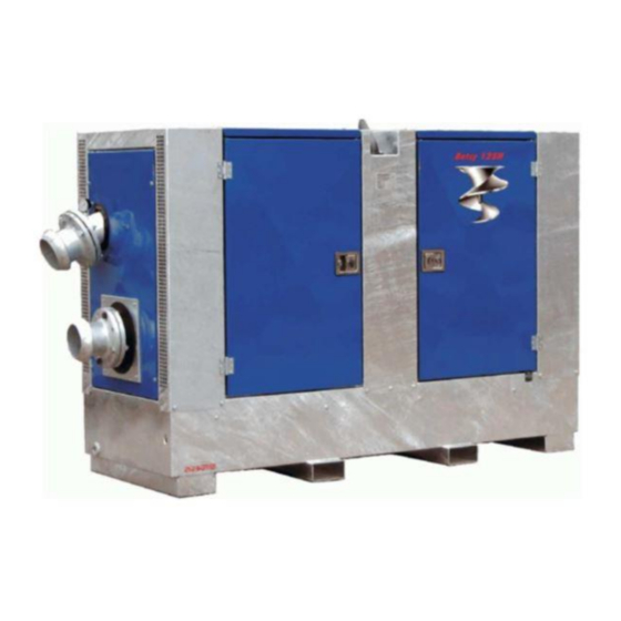
- Page 2 Diesel centrifugal pump in silenced canopy Technical specification: Intended use Sewerage and drainage water pumping Make / Type Eekels / Betsy 125H Maximal flow 385 m3 / h, see curve Maximal head 32 mwc, see curve Maximal suction lift 8,5m Suction connection 6’’...
- Page 4 User manual Betsy 125H...
-
Page 5: Table Of Contents
Specification and dimensions ......................6 Performance curve .......................... 7 Safety instruction ..........................8 Warning stickers ........................8 Lifting instructions Betsy 125H pump unit .................. 10 Moving the pump unit with a forklift ..................11 Pump unit installation ........................12 Outdoor use ..........................13 Indoor use .......................... -
Page 6: Description, Application And Working Principle
1 Description, application and working principle Description WARNING: This manual is intended to give Important Information that must be followed during Storage, Transportation, Installation, Operation and Maintenance of the Pump-Set. We therefore recommend that this manual is read carefully before the Pump-Set is put into operation. To prevent damage being caused by inappropriate or incorrect use, or by being used outside the normal operating parameters of the Pump-set, the Instructions in this manual must be followed. -
Page 7: Construction
Construction The pump consists of the following main components: 1. Canopy 2. Pump and engine frame 3. Fuel tank 4. Engine 5. fuel system 6. engine speed control 7. engine air filter assembly 8. exhaust silencer assembly 9. fly wheel shaft assembly 10. -
Page 8: Unintended Use
Unintended use – It is not permitted to use the pump for pumping flammable and/or explosive substances. – It is not permitted to deploy a standard pump or pump unit in an environment in which there is a danger of fire and/or explosion. –... -
Page 9: Specification And Dimensions
Specification and dimensions Standard technical specification Pump type......Betsy 125H Max. flow......385 m3/hour Max. head......32 mwc Dimensions L x W x H ..2612 x 1040 x 1756 mm Dry weight…………………..1900 kg Fuel tank ......300 ltr Solids handling ....100 mm Engine Engine brand ....... -
Page 10: Performance Curve
Performance curve... -
Page 11: Safety Instruction
Safety instruction This manual contains warning and safety symbols. Do not ignore the instructions. They are provided for the benefit of your health and safety and to prevent damage to the environment and the pump unit. DANGER When the danger symbol with the text DANGER is shown, it is accompanied by information that is of great importance for the safety of everyone concerned. - Page 12 Label for the transport of hazardous materials (hazardous goods) in accordance with the safety standard for the transport of hazardous goods. The UN 1202 class 3 placard indicates the presence of gas oil, diesel fuel or light heating oil. Diesel is hazardous to the environment, with substantial remediation costs if it leaks into a drain, waterway or the ground.
-
Page 13: Lifting Instructions Betsy 125H Pump Unit
Lifting instructions Betsy 125H pump unit DANGER Never walk under a raised load. This can result in a life-threatening situation. WARNING Always disconnect all external connections before moving the pump unit. WARNING Neither the lifting eye on the engine nor the lifting eye of the (bare shaft) pump may be used for transport of the pump unit. -
Page 14: Moving The Pump Unit With A Forklift
DANGER NEVER move or lift the pump unit by the angle profiles on top of the enclosure or stacking frame. Moving the pump unit with a forklift Forklift pockets (if present) can be used for moving the pump unit with a forklift. The forks of the forklift must be inserted into these pockets to lift the pump unit. -
Page 15: Pump Unit Installation
Pump unit installation Placement – general WARNING Failure to follow the guidelines for the placement and installation of the pump unit can result in danger to the user and/or severe damage to the pump or pump unit. Eekels pumps is not responsible for accidents and damage that result from failure to follow the guidelines in this manual. -
Page 16: Outdoor Use
– Install shields to prevent contact with hot surfaces > 70 °C (158 °F). Affix warning symbols where necessary. – If the pump and motor are provided separately, check the alignment after installation. – When pumping hot liquids make sure there is sufficient air circulation to prevent bearings and lubricants from overheating. -
Page 17: Indoor Use
Indoor use In addition to the general instructions, the following additional requirements must be met: − Ensure that the area has adequate ventilation. − Make sure the exhaust gases are discharged outdoors. − Ensure that there is sufficient free space around the air intake so the engine is able to draw as much air as it needs. -
Page 18: Daily Maintenance Of The Pump
Daily maintenance of the pump Note Perform daily maintenance pump must be switched off. The sight glasses must be at least half filled and oil may not be discolored. 1. Check the oil level and clarity of the oil in the pumps seal chamber (1). If the oil is not clear but white, its means that the oil contains water. -
Page 19: Priming The Fuel System
Priming the fuel system WARNING Always check fuel level in fuel tank. Don’t start the pump when fuel is running low. In this case air can get in fuel system. Prime the fuel system before starting the engine for the first time, after the fuel tank has been drained completely or after replacement of the fuel filter(s). -
Page 20: Engine Oil Level Check
Engine oil level check WARNING Hot oil and components can cause personal injury. Do not allow hot oil or hot components to contact the skin. Note Perform this maintenance engine must be stopped. The engine must be in horizontal position before adding oil or checking the oil level. Pull out dipstick (4) and add engine oil of the correct specification and viscosity up to the’’max’’... -
Page 21: Automatic Level Control
Automatic level control When water level is rising not fast enough and needed to pump liquid several times in day or hour its possible to use automatic level control switches (1,2,3) Cable with red marking (1) is Maximum level, cable with blue marking is Minimum level, but cable in green marking (3) is grounding. -
Page 22: Control Panel Betsy 125H
Control panel Betsy 125H Dynamo warning lamp Hour counter Water – Bentonite switch Ignition switch Selector switch for Manual – 0 – Automatic operation Rood = red, electrode pin position High Blue = blue, electrode pin position Low Yellow green = green and yellow (earth) electrode pin position Bottom. -
Page 23: Pump Unit Preparation For Starting
Pump unit preparation for starting Check the oil level and clarity of oil in the pump seal chamber. If the oil is not clear but white, this means that the oil contains water. Drain this mixture, check the seal and fill the seal chamber with fresh oil. -
Page 24: Starting (Manual)
Starting (manual) 1. Check the pump type (type plate) and the characteristics of the pump unit, such as: rpm, operating pressure, power consumption, operating temperature, etc. Check whether the pump unit is placed in accordance with the instructions. Pay particular attention to the area around the pump unit. - Page 25 11. Turn the switch (3) ‘’H – 0 – A’’ in the position HAND. 12. Turn the throttle (4) to maximum speed. 13. Turn the switch (5) to position 1. Engine will start.
- Page 26 14. Regulate engine speed with throttle (4), to necessary speed WARNING If vibration occurs during starting, stop the pump immediately and eliminate the cause before starting again. WARNING If the pump vacuum lift is set too high, cavitation in the pump set is possible and this can be recognized by High levels of vibration, a crackling noise in the pump, decreased capacity and pressure.
-
Page 27: Starting (Auto)
Starting (auto) 1. Check the pump type (type plate) and the characteristics of the pump unit, such as: rpm, operating pressure, power consumption, operating temperature, etc. Check whether the pump unit is placed in accordance with the instructions. Pay particular attention to the area around the pump unit. - Page 28 12. Turn the switch (3) ‘’H – 0 – A’’ in the position AUTOM. 13. Plug automatic level control socket (4), set the minimum an maximum electrodes 14. Turn the throttle (5) to maximum speed.
- Page 29 15. Turn the switch (6) to position 1. Engine will start if all electrodes are under water. 16. Regulate engine speed with throttle (4), to necessary speed WARNING If the pump vacuum lift is set too high, cavitation in the pump set is possible and this can be recognized by High levels of vibration, a crackling noise in the pump, decreased capacity and pressure.
-
Page 30: Stopping
Stopping 1. Turn the switch “H – 0 – A” (3) to position “0”. 2. Turn the starter key (4) to position 0. Engine will stop. 3. Observe whether the system comes to a gradual, smooth stop. 4. When you suspect that the liquid is beginning to freeze, drain the pump while the medium is still in the liquid state. -
Page 31: Draining The Pump When There Is Danger Of Freezing
13 Draining the pump when there is danger of freezing WARNING If there is a danger of freezing, a pump used to pump a liquid that may freeze must be drained (while at a standstill). 1. Turn off the engine and open canopy draining ports (covers / plugs) (1). 2. -
Page 32: Troubleshooting
14 Troubleshooting WARNING In the event of a malfunction or abnormal operation, shut off the pump or pump unit immediately to prevent a dangerous situation and/or damage (possibly severe) to the pump or pump unit. Inform to responsible persons. Determine the cause of the malfunction. Resolve the problem before restarting the pump Problem Cause... - Page 33 The liquid has a higher s.g. or viscosity Change temperature of liquid, if possible. than that for which the pump is intended Otherwise: use a different type of pump WARNING If appear some pump defect and cannot find fault immediately contact Uprent technical department...