
Related Manuals for I-Tech RKP2415-1602


Summary of Contents for I-Tech RKP2415-1602
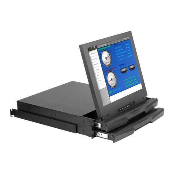
- Page 1 User Manual RKP2415 / 2417 / 2419 - 1602 2U 15” / 17” / 19” Rackmount LCD Keyboard Drawer with PS/2 2-Console KVM Switch...
-
Page 2: Table Of Contents
2. Introduction 3. Features 4. Package Contents 5. Optional Accessories 6. Peripheral Products 7. Important Safeguards 8. Structure Diagram 9. Dimension Diagram RKP2415-1602 RKP2417-1602 RKP2419-1602 10. LCD Session LCD Membrane Diagram LCD OSD Control Resolution Settings 11. KVM Session Front View... -
Page 3: Introduction
RKP2415 / RKP2417 / RKP2419 2. Introduction RKP Series is a combination of keyboard, mouse and monitor into a drawer, with features such as flip-up design, adjustable brackets, built in LCD OSD to provide effective assistant for an administrator to control PC system. RKP Series provides cost effective for your limited IT budget over using CRT and rack mounting. -
Page 4: Package Contents
RKP2415 / RKP2417 / RKP2419 LCD Monitor Drawer with PS/2 KVM Switch (Two Consoles) User Manual DC Power Adapter Power Cord Mounting Bracket Fasteners CD-6 3-in-1 KVM cable Before Unpacking It is very important to locate the LCD Keyboard Drawer in a suitable environment. The surface for placing and fixing the LCD Keyboard Drawer should be stable and level ●... -
Page 5: Optional Accessories
RKP2415 / RKP2417 / RKP2419 5. Optional Accessories KVM Cable CD-6 / 10 / 15 Cascade Cable CA-6 / 10 / 15 Conversion Adapter SUN-31 6. Peripheral Products Model CV-801 CV-1601 Rev. : 1.0 6ft / 10ft / 15ft 3-in-1 KVM cable 6ft / 10ft / 15ft PS/2 3-to-3 Cascade cable SUN / iMAC USB to PS/2 adapter Description... -
Page 6: Important Safeguards
RKP2415 / RKP2417 / RKP2419 7. Important Please read all of these instructions carefully before you use the device. Save this manual for future reference. Unplug the LCD Keyboard Drawer from the power outlet before cleaning. ● Do not spray liquid cleaners or aerosol directly on the device. Wet a cloth with ●... -
Page 7: Structure Diagram
RKP2415 / RKP2417 / RKP2419 PS/2 keyboard Aluminium front panel Class A active matrix TFT LCD panel Analog to digital signal converter board Rear metal case LCD inverter LCD membrane Ball bearing telescopic slides with stopper Adjustable mounting bracket KVM membrane & KVM switch board Rev. -
Page 8: Dimension Diagram
RKP2415 / RKP2417 / RKP2419 User Manual 9. Dimension Diagram RKP2415-1602 2U 15” LCD Keyboard Drawer with PS/2 KVM (Two Consoles) 15” LCD Rev. : 1.0... -
Page 9: Rkp2417-1602
RKP2415 / RKP2417 / RKP2419 User Manual 9. Dimension Diagram RKP2417-1602 2U 17” LCD Keyboard Drawer with PS/2 KVM (Two Consoles) 17” LCD Rev. : 1.0... -
Page 10: Rkp2419-1602
RKP2415 / RKP2417 / RKP2419 User Manual 9. Dimension Diagram RKP2419-1602 2U 19” LCD Keyboard Drawer with PS/2 KVM (Two Consoles) 19” LCD Rev. : 1.0... -
Page 11: Lcd Session
RKP2415 / RKP2417 / RKP2419 User Manual Session Rev. : 1.0 P.10... -
Page 12: Lcd Membrane Diagram
RKP2415 / RKP2417 / RKP2419 10. LCD Session LCD Membrane Diagram Main Menu Bright / Contrast To enter into the Bright, Black level & Contrast sub-menu ● Auto Adjust To perform automatic optimisations of all functions ● An “ Adjusting” message is displayed during the process ●... - Page 13 RKP2415 / RKP2417 / RKP2419 10. LCD Session Bright / Contrast 1. Brightness To perform brightness adjustment of the input RGB signal ● Use the Left & Right button to adjust and button ● 2. Contrast To adjust the contrast level of the input signal ●...
- Page 14 RKP2415 / RKP2417 / RKP2419 10. LCD Session MISC 1. Information The first header row shows the current resolution setup ● The second header row shows the horizontal frequency of the current ● input signal The third header row shows the vertical frequency of the current input ●...
-
Page 15: Resolution Settings
RKP2415 / RKP2417 / RKP2419 10. LCD Session Resolution Settings For Microsoft Windows Step 1 – Press right click on the desktop Step 2 – Choose “Properties” Step 3 – Change the “Screen Resolution” Step 4 – Change the “Screen refresh rate” Rev. -
Page 16: For Sun Servers
RKP2415 / RKP2417 / RKP2419 10. LCD Session Resolution Settings For SUN Servers Resolution configuration procedures should be run by qualified SUN ● server administrator Sun Servers are using resolution at 1152 x 900 x 76Hz. ● Supported resolution mode for 15” LCD: ●... -
Page 17: Kvm Session
RKP2415 / RKP2417 / RKP2419 User Manual Session Rev. : 1.0 P.16... -
Page 18: Front View
RKP2415 / RKP2417 / RKP2419 11. KVM Session Front View Online Channel LED Indication Selected Channel Channel select button - Press to select channel from 1 – 8. Shift button Online Channel Bank no. Bank button Rev. : 1.0 Selected Channel Channel Select Button - Displayed channel on monitor &... -
Page 19: Rear View
RKP2415 / RKP2417 / RKP2419 11. KVM Session Rear View Power RKP24XX-1602 (Local Console) DC Power Cascade Port LAN Port Channel Port RKP24XX-1602 (Remote Console) • DC Power ‚ LAN Port ƒ Keyboard Port „ VGA Port … Mouse Port Rev. -
Page 20: Installation Steps
RKP2415 / RKP2417 / RKP2419 11. KVM Session Installation Steps Before installation, please make sure all computers are turned on and its operating system are running properly with keyboard and mouse. Connect the 3-in-1 KVM cable to the one of your server. ●... -
Page 21: Cascading
RKP2415 / RKP2417 / RKP2419 11. KVM Session Cascading Using a CA-6 / 10 / 15 cascade cable to connect from Bank 1’s “Cascade port” to Bank 2’s “Console port”. After connected please press “Bank” & “Channel” button on the front of the PS/2 KVM switch to reset the KVM switch. -
Page 22: Start Up
RKP2415 / RKP2417 / RKP2419 12. Start Up The channels that have PC connected and it is switch on will have a green LED on that channel. The red LED will indicate the selected channel. 7 segments LED will display the bank number. Press channel button to select the channel. -
Page 23: Hotkey Command Operation
RKP2415 / RKP2417 / RKP2419 12. Start Up Hot-key Command Operation Calling OSD Menu Scroll Switch to Previous Port (powered on PC only) Scroll Switch to Next Power On Port (powered on PC only) Scroll Switch to Previous Bank Scroll Switch to Specific Port Scroll Example :... - Page 24 RKP2415 / RKP2417 / RKP2419 12. Start Up HotKey Command Operation Switch to Next Bank Scroll Enable / Disable beeper sound Scroll Note: Auto Scan for Powered on PC Scroll Reset to factory Default Setting Scroll Note: 10. Find Port by name Scroll Note: Rev.
-
Page 25: Osd Structure Diagram
RKP2415 / RKP2417 / RKP2419 12. Start Up OSD Structure Diagram BANK : 1 BANK : 1 ® SYSTEM 03 SYSTEM ® SYSTEM 03 ® SYSTEM 05 ® SYSTEM 05 SYSTEM 07 OSD : 1 0 SEC. CHANGE PASSWORD OSD : 1 0 SEC. CHANGE PASSWORD SCAN: 1 0 SEC. -
Page 26: Settings Session
RKP2415 / RKP2417 / RKP2419 12. Start Up KVM Settings Session ● ● Scan ● ● Change Password ● ● ● ● ● ● ● Console On/OFF ● ● ● Escape ● Rev. : 1.0 OSD Menu on screen time default is 10 seconds. -
Page 27: Faq
RKP2415 / RKP2417 / RKP2419 13. FAQ 1. The recommended distance of VGA cable is 5 meters (maximum) without ghosting and degradation. Normally, the cable length is based on driver capacity of your VGA card. If you need longer VGA cable, please use VGA extender to accomplish your applications. 2. - Page 28 RKP2415 / RKP2417 / RKP2419 13. FAQ If you forget the “password” of the switch (default is 00000000), please contact your supplier. CAT.5 Console Receiver power LED is not ON, to make sure power adapter is connected to KVM CAT.5 receiver. No video signal is displayed on the remote monitor.
-
Page 29: Technical Specification
RKP2415 / RKP2417 / RKP2419 14. Technical Specifications PC port PC Port interface PC Computer Interface Cascade Port Connector KVM Cable Connection PC Selection On screen display control Scan intervals Keyboard and mouse emulation VGA resolution (Max.) CAT.5 cable length (Max.) Bandwidth Cascade Level (Max.) - Page 30 Auto Config., Input Select, Multi-Window Clear EEPROM, OSD adjust 12V DC Adapter 15-pin D-Sub Connector RKP2415-1602 : 439W x 88H x 440D mm RKP2417-1602 : 439W x 88H x 440D mm RKP2419-1602 : 442W x 88H x 480D mm RKP2415-1602 : 12.5kg RKP2417-1602 : 13.5kg...
Need help?
Do you have a question about the RKP2415-1602 and is the answer not in the manual?
Questions and answers