Table of Contents
Advertisement
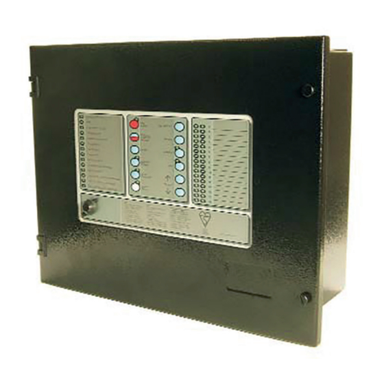
Marine Fire Detection/Alarm Control Panel and Repeater
© 2014 Thorn Security Ltd
Registered Company: Thorn Security Ltd. Registered Office: Dunhams Lane Letchworth Garden City Hertfordshire SG6 1BE
EQUIPMENT:
PUBLICATION:
ISSUE No. & DATE:
TYCO T1200-C
Application Guide
T1200-C
MARINEC-P-A
3
02/14
PAGE 1 of 67
Advertisement
Table of Contents


Need help?
Do you have a question about the T1200-C Series and is the answer not in the manual?
Questions and answers