Table of Contents
Advertisement
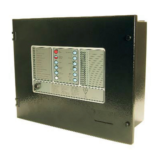
Marine Fire Detection/Alarm Control Panel and Repeater
© 2014 Thorn Security Ltd
Registered Company: Thorn Security Ltd. Registered Office: Dunhams Lane Letchworth Garden City Hertfordshire SG6 1BE
EQUIPMENT:
PUBLICATION:
ISSUE No. & DATE:
TYCO T1200-C
Application Guide
T1200-C
MARINEC-P-A
3
02/14
PAGE 1 of 67
Advertisement
Table of Contents

Related Manuals for Tyco T1216-C


Summarization of Contents
General Description of T1200-C Panels
Cabinet Specifications for T1200-C
Details enclosure construction, material gauge, and paint finish for the panels.
Order Codes and Descriptions for T1200-C
Lists Tyco Part Numbers, their descriptions, and compatible standby SLA batteries.
Replacement Part Order Codes for T1200-C
Provides part numbers for replacement components and their applications within the T1200 range.
Optional Language Display Inserts for T1200-C
Lists part numbers for language insert sets for different panel models.
Optional Door Stay Assembly for T1200-C
Details the part number and usage for an optional door stay assembly.
Fire Detection and Alarm Panel Description
C1626 4 Zone Motherboard Features
Describes the C1626 motherboard, its features, and its use in T1204 panels and repeaters.
C1627 16 Zone Motherboard Features
Details the C1627 motherboard, common to T1216-C and T1232-C panels, and its features.
C1632 32 Zone Expansion Board
Explains the C1632 board, providing additional zones for the T1232-C panel.
Display Boards: C1628 & C1629
Describes display boards for user indications and controls, common to different panel types.
Display Overlay and Inserts
Details the display overlay and text inserts used for user controls and indications.
C1631 Repeater Interface Board
Explains the optional RS485 serial interface board for repeater communication.
C1665 Muster Interface Board
Describes the optional board for fault-monitored links between panels and repeaters.
Output Expansion System Overview
Details the expandable modular output system comprising an Output Interface Board and output boards.
C1630 Output Interface
Describes the PCB that provides the communication path for output expansion modules.
C1714 Voyage Data Recorder Interface Module
Explains the VDR output module for signalling critical conditions to a Voyage Data Recorder.
Functional Specification of T1200 Panels
T1200 Panel Input/Output List
Lists and compares the inputs and outputs available for T1204, T1216-C, and T1232-C panels.
T1200 Panel Features List
Details features like enclosures, battery charging, zone configuration, outputs, and inputs.
T1200-C Expansion Board and Display Features
T1200-C1632 16-zone Expansion Board Features
Illustrates and describes the features of the C1632 16-zone expansion board.
T1200-C Display Board Features
Illustrates and describes the features of the T1200-C display board, including controls and configuration.
C1714 Voyage Data Recorder Interface Module
C1714 VDR Interface Module Description
Details the module's function of providing outputs for VDR recording of panel events.
VDR RS422 Output Sentence Structure
Describes the various sentences sent to the VDR regarding panel status.
ZONAL FIRE Sentence Structure
Details the format and example of the zonal fire status sentence transmitted to the VDR.
ZONAL FAULT Sentence Structure
Details the format and example of zonal fault status sentences transmitted to the VDR.
GENERAL FAULT Sentence Structure
Details the format and example of general fault status sentences transmitted to the VDR.
MAINS FAULT Sentence Structure
Details the format and example of mains fault status sentences transmitted to the VDR.
BATTERY FAULT Sentence Structure
Details the format and example of battery fault status sentences transmitted to the VDR.
ZONAL DISABLEMENT Sentence Structure
Details the format and example of zonal disablement and enablement sentences transmitted to the VDR.
STATUS MESSAGE Sentence Structure
Details the format and example of status messages transmitted to the VDR for communication checks.
HOURLY STATUS MESSAGES
Details the format and example of hourly status messages transmitted to the VDR.
COMMS FAULT Sentence Structure
Details the format and example of communication fault sentences transmitted to the VDR.
PANEL RESET Sentence Structure
Details the format and example of panel reset messages transmitted to the VDR.
T1200 Interface Module Features
C1630 Output Expansion Interface Features
Describes the features and DIL switch settings for the C1630 Output Expansion Interface.
C1631 Repeater Interface Board Features
Describes the features and configuration switch settings for the C1631 Repeater Interface Board.
C1665 Muster Interface Board Features
Describes the features and field wiring terminals for the C1665 Muster Interface Board.
Power Supplies for T1200 System
General Power Supply Information
Details general features of all PSUs, including battery charging, testing, and disconnect.
T1204A1/A2 AC Powered PSUs
Describes the T1204 PSUs, their supply input, output, and fusing.
PS40-1-09 24 Vdc PSU for T1204
Describes the PS40-1-09 PSU for 24Vdc installations and its fan.
PS136-1-09 AC Powered PSUs for T1216-C/T1232-C
Describes the PS136-1-09 PSU for 110/230Vac installations and its fan.
Power Supply Input and Output Specifications
Details input supplies, DC output, fusing, battery charger, and charger monitor functions.
Battery Monitoring and Health Functions
Covers battery monitoring, testing, disconnect, and health functions for PSUs.
PSU Visual Indications and Fault Outputs
Lists PSU LEDs and details the two open collector fault outputs and their conditions.
Power Supply Safety and Mechanical Protection
Provides warnings about safety earth connection and protective cages for PSUs.
T1200 Power Supply Features and Connections
Shows the layout and connections for the PS40-1-09 and PS136-1-09 power supplies.
Compatible Field Devices for T1200
Field Device Part Numbers and Specifications
Lists compatible field devices with manufacturer, part number, description, and current draw.
User Functions Overview for T1200 Panels
User Indications on T1200 Panels
Lists general and zone location indicators, their colours, and operating conditions.
T1200 User Controls and Functionality
Details user controls like Manual Fire Alarm, Silence/Resound, Reset, and their functionalities.
Zone/Output Selection for Disablement/Test
Explains how to select zones/outputs for disablement, enablement, or test using the cursor select feature.
Zone and Output Disablement/Re-enablement
Describes disabling/re-enabling zones and specific outputs like sounders, fire output, etc.
Detector Zone One Man Test
Explains the Detector Zone One Man Test feature, its operation, and fire output inhibition.
Alarm Sounder One Man Test
Details the Alarm Sounder One Man Test feature for intermittent sounder operation.
Delay Mode Operation (On/Off)
Explains how to turn the delay mode on/off in standard and crew alert modes.
Overriding the Delay Mode
Describes how to override the delay mode using panel buttons or manual call points.
Adjustable Display LED Brightness
Explains how to adjust the brightness of panel and repeater LEDs.
Engineer Functions Overview for T1200 Panels
Engineer's Configuration Process
Details engineer configuration using DIL switches and the select feature.
Zone/Output Selection for Configuration
Explains the process of selecting zones/outputs for configuration using the cursor.
Configuring Delayed Outputs
Describes how to configure outputs as delayed or non-delayed.
Configure Machinery Space Zones
Explains how to configure zones as Machinery Space Zones or Standard Zones.
Configure Non-Latching Zones
Details how to configure zones as Non-latching Fire Zones or Latching Fire zones.
Configure Intrinsically Safe Zones
Explains how to configure zones as Intrinsically Safe (I.S.) zones and related warnings.
Mixed I.S. and Non-I.S. Zones Configuration
Discusses requirements for zones containing mixed Intrinsically Safe and non-I.S. devices.
T1200 Delay Mode Feature
Explains the delay mode feature for automatic fire detector responses and its limitations.
Selection of Outputs to be Delayed
Refers to section 17.3 for details on selecting outputs for delayed operation.
Selectable Zonal or General Alarm Sounder Operation
Explains how to select between Zonal or General Alarm modes for sounder operation.
Pulse Non-Alarm Zones for Sounders
Describes the DIL switch setting for zonal sounder response type.
Alarms in Crew Areas Mode
Explains the Crew Area Alarm mode and its effect on sounder operation and delay.
Delay Restart DIL Switch Functionality
Details the DIL switch for controlling delay restart behavior in Crew Mode.
Selectable Muster/Manual Fire Alarm Sounder Operation
Explains how to set up Muster or Manual Fire Alarm sounder response modes.
Inhibit Fire Protection on Non-Latched Zones
Explains the DIL switch for inhibiting Fire Protection output on non-latched zones.
Delay Alarm Silence and Reset Controls
Details the DIL switch that prevents alarm silence and reset for a period after a fire alarm.
Delay ON Auto DIL Switch
Explains the DIL switch for zone coincidence with the Watermist system.
Alarms on Evac Only DIL Switch
Details the DIL switch for sounders operating only in Manual Fire Alarm or muster conditions.
Silence before Reset DIL Switch
Explains the DIL switch that determines when the panel can be reset from a fire condition.
Continuous or Pulsed Sounder Operation
Details the DIL switch for selecting continuous or pulsed sounder operation.
Silent Zone Test DIL Switch
Explains the DIL switch for selecting silent response in One Man Test Mode.
Buzzer Disable DIL Switch
Details the DIL switch for enabling/disabling the panel buzzer.
Latched Faults DIL Switch
Explains the DIL switch for enabling/disabling the latched fault indication mode.
Repeater Configuration Settings
Describes how DIL switches configure the panel for communication with repeaters.
Output Relay Configuration Options
Details how output relays can be configured as powered/monitored or volt-free.
Panel Repeaters Overview
Earth Fault Monitoring Configuration
Explains how to disable earth fault monitoring by removing a jumper link.
Repeater User Indications
Lists general indicator sections for repeaters, their colours and operating conditions.
Repeater User Controls and Functionality
Details repeater user controls such as Manual Fire Alarm/Muster, Reset, and their functionalities.
Circuit Connection Details for T1200 Panels
T1204 (C1626) 4-Zone Panel Termination Details
Shows field terminations for the T1204 4-zone panel, including inputs and outputs.
T1216-C/T1232-C Motherboard Termination Details
Shows field terminations for the T1216-C and T1232-C motherboards.
32-Zone Expansion Board Termination Details
Shows field terminations for the C1632 17-32 zone expansion board.
T1200 Panel Outputs and Inputs
Auxiliary Supply Functionality
Explains the auxiliary supply output available for external field equipment.
Fire Protection, Fire Output, and Fault Output Signals
Details the factory-set powered/monitored outputs and site configurable volt-free relay outputs.
Use of Auxiliary Inputs
Explains the use of auxiliary inputs for remote operation of functions like Class Change and Remote Reset.
Sounder Circuits Specifications
Details sounder circuit ratings, polarity monitoring, and alarm circuit configuration.
Electrical Design of Detection Zones
Maximum Number of Devices on a Zone
Details maximum device limits per zone based on quiescent current and EN54 recommendations.
Intrinsically Safe Zones Wiring and Installation
Warns about I.S. zone wiring and installation compliance with guidelines.
T1200-C Input and Output Specification
Detection Zone Inputs Specifications
Details zone input specifications, including thresholds and cable requirements.
Ancillary Inputs Specifications
Specifies ancillary inputs like Zonal Fire Outputs, Class Change, and Remote inputs.
Output Specifications
Details output specifications for Evacuate, Buzzer, Disablement, Reset, Fire, Fire Protection, and Fault Routing.
Auxiliary Supply Specifications
Specifies auxiliary supply current, voltage, protection, and cable requirements.
Repeater Output Specifications
Details repeater output specifications, including number, length, protocol, and cable types.
Appendix Information for T1200-C
EN54 Optional Functions with Requirements
Lists EN54 optional functions supported by the T1200-C panel.
Ancillary Functions Not Required By EN54
Lists auxiliary functions offered by the panel that are not required by EN54.
Power Supply Load Calculation
Provides a method to calculate the maximum power supply load for the panel.
Minimum Standby Battery Capacity Calculation
Details how to calculate the minimum required standby battery capacity for the control panel.
Need help?
Do you have a question about the T1216-C and is the answer not in the manual?
Questions and answers